
PNEUMATIC STAMPING MACHINE
Department of mechanical engineering-ATME mysore Page1
PNEUMATIC “TAMPING MACHINE
A undergraduate project report submitted toVisvesvaraya Technological Universityin partial fulfillment
of the requirements for the award of the degree of
BACHELOR OF ENGINEERING
In
MECHANICAL ENGINEERING
Submitted By
JAGADISH S USN: 4AD12ME030
KARAN KUMAR S USN: 4AD12ME032
MANJU M P USN: 4AD12ME043
MOHAN KUMAR S USN: 4AD12ME052
Under the Guidance of

PNEUMATIC STAMPING MACHINE
Department of mechanical engineering-ATME mysore Page2
Mr. RAVI KUMAR S
Assistant professor
Dept of Mechanical Engineering
A T M E College of Engineering
Mysuru
Department of Mechanical Engineering
A T M E COLLEGE OF ENGINEERING
MYSURU-570028
2015-2016

PNEUMATIC STAMPING MACHINE
Department of mechanical engineering-ATME mysore Page3
A T M E College of Engineering
Mysuru-570028
(Affiliated to Visvesvaraya Technological University, Belgaum)
Department of Mechanical Engineering
Certificate
This is to certify that project work entitled PNEUMATIC STAMPING MACHINEis a bona-fide
work carried out by Mr.JAGADISH S (4AD12ME030), Mr. KARAN KUMAR S (4AD12ME032),
Mr.MANJU M P (4AD12ME043), Mr. MOHAN KUMAR S (4AD12ME052), in partial fulfillment for
the award of Bachelor of Engineering in Mechanical Engineering of the Visvesvaraya Technological
University, Belagavi during the year 2015-2016. It is certified that all corrections/suggestions indicated
for Internal Assessment have been incorporated in the report deposited in the departmental library. The
project report has been approved as it satisfies the academic requirements in respect of project work
prescribed for the said degree.
Project Guide Head of the Department

PNEUMATIC STAMPING MACHINE
Department of mechanical engineering-ATME mysore Page4
(Mr. RAVI KUMAR S) (Mr. Srinivasa K)
Assistant Professor Associate Professor, H O D,
Dept. of Mechanical Engineering Dept. of Mechanical Engineering
ATMECE, Mysuru. ATMECE, Mysuru.
(Dr.LBasavaraj)
Principal
ATMECE, Mysuru.
External Viva
Name of Examiners Signature with date
1………………… …………………….
2.………………… …………………....

PNEUMATIC STAMPING MACHINE
Department of mechanical engineering-ATME mysore Page5
ABSTRACT
The pneumatic system has gained a large amount of importance in last few decades. This
importance is due to its accuracy and cost. It can be operated easily with semi-skilled operators
.This convenience in operating the pneumatic system has made us to design and fabricate this
unit which is operated by pneumatics as our project. The project is further elaborated to the
function of pneumatics with their behavior in several aspects. This machine has an advantage of
working even at low pressures, that is even pressure of 8 bars is enough for the operation. The
pressurized air passing through the cylinder forces the piston out whose power through linkages
is transmitted to the work piece. The work piece thus got it for the required dimensions and the
impression is made on it.
The stamping machine uses a mechanism of quick retrieval done by acting of pressurized air
inside of it. The operation of the compressed air is done by using a solenoid valves. This project
also elaborates about the other applications just by changing its arm.

PNEUMATIC STAMPING MACHINE
Department of mechanical engineering-ATME mysore Page6
CONTENTS
Chapter 1 : Introduction 01-04
1.1 Overview of the project 01
1.2 Problem statements 02
1.3 Objective 02
1.4 Methodology 02
1.5 Working principle and components 03
Chapter 2 : Literature Survey 05-11
2.1 Introduction 05
2.2 Pneumatic System 05
2.3 Principles and Maintenance 06
2.4 Application of Pneumatics 06
2.5 Advantages of Pneumatic system 06
2.6 Area of Application of Pneumatic system 07
2.7 Different types of Pneumatic Stamping Machine 09
Chapter 3 : Component Details 12-16
3.1 Pneumatic System 12
3.2 Compressor 14
3.3 Directional Control Valve 15
3.4 Pressure regulating Component 16
Chapter 4 : Detail Design 17-23
4.1 Design Calculation 17
4.2 Punch Design 18
4.3 Designing of cylinder 19
4.4 Part Drawings and Assembly 21

PNEUMATIC STAMPING MACHINE
Department of mechanical engineering-ATME mysore Page7
Chapter 5 : Fabrication 24-34
5.1 Supporting Frames 24
5.11 C Frame 24
5.12 Base Frame 26
5.2 Pneumatic Cylinder 27
5.3 Piston 29
5.4 Connecting Rod 30
5.5 Punch Holder 31
5.6 Direction Control Valve 32
5.7 Pressure Regulating Valve 33
5.8 Assembly 34
Chapter 6 : Project Cost 35
Conclusion 36
References 37
LIST OF FIGURES
Chapter 1 :
1.1Schematic diagram of Pneumatic Stamping Machine 03
Chapter 2 :
2.1 Schematic diagram of pneumatic control system 08
Chapter 3 :
3.1 Cross section of a single acting cylinder 12
3.2 (a) Single acting cylinder 13
3.2 (b) Pneumatic symbol of a single acting cylinder 13
3.3 Cross section of a double acting cylinder 13
3.4 (a) Double acting cylinder 14
(b) symbol of double acting cylinder 14
3.5 (a) Compressor used in schools 14

PNEUMATIC STAMPING MACHINE
Department of mechanical engineering-ATME mysore Page8
(b) Compressor used in laboratories 14
(c) Pneumatic symbol of a compressor 14
3.6 Describing a 5/2 directional control valve 15
3.7 (a) 2/2 directional control valve 16
(b) Cross section 16
(c) Pneumatic symbol of 2/2 directional control valve 16
3.8 Pneumatic symbols of the pneumatic components within a pressure
Regulating Component 16
Chapter 4 :
4.1 Pneumatic circuit diagram 20
4.2 C Frame 21
4.3 Pneumatic Cylinder 21
4.4 Piston 22
4.5 Connecting rod 22
4.6 Punch 23
4.7 Pneumatic Stamping Machine Assembly 23
Chapter 5 :
5.1 C-frame 24
5.3 Base Frame 26
5.4 pneumatic cylinder 27
5.5 Piston 29
5.6 Connecting Rod 30
5.7Punch holder 31
5.8 Direction control valve 32
5.9 pressure regulating valve 33
5.10 Assembly 34
LIST OF TABLES

PNEUMATIC STAMPING MACHINE
Department of mechanical engineering-ATME mysore Page9
Chapter 4 :
4.1 Press Force Calculations for Aluminum Sheet of Different Thickness 17
4.2 Percentage reduction Calculations after providing shear on tool for
Aluminum Sheet 19
Chapter 5 :
5.1 Dimensions of C- frame 25
5.2 Dimensions of Base frame 27
5.3 Dimensions of Pneumatic Cylinder 28
5.4 Dimensions of Piston 29
5.5 Dimensions of Connecting rod 31
5.6 Dimensions of Punch holder 32
Chapter 6 :
6.1 Cost Estimation 35

PNEUMATIC STAMPING MACHINE
Department of mechanical engineering-ATME mysore Page10
Chapter 1
Introduction
1.1 Overview of the project
A pneumatic pressing machine is always a better choice than a hydraulic pressing machine for
the production of similar products if it is suited for the method. It is comparatively more
economical for production of large quantities of products as it uses compressed air rather than
some hydraulic fluid which is rather expensive. A pneumatic pressing machine uses compressed
air to generate high pressure to be applied on the piston. A direction control valve controls the
directional flow of air into and out of the cylinder. Hoses are used for air transmission from the
pneumatic cylinder to the press assembly. The high pressure air fed to the press plate, forces it on
the material and as the presses descends upon the sheet, the pressure exerted by the press first
cause the plastic deformation of the sheet. Since the clearance between the press and the circular
plate is very small, the plastic deformation takes place in a localized area and the required
impression is created on the sheet metal.
The Pneumatic pressing machine is developed using various components. The components are
pneumatic cylinder, pressure regulator, direction control valve, flow control valve, compressor
mounting table. The cylinder is used for up and down motion of the press tool which performs
the pressing operation on the sheet metal.
The compressor provides compressed air to the cylinder, which causes movement of the piston
rod. Pneumatic automation components extensively use sealing material made out of rubber
compounds.
For efficient and trouble free working of these seals, they need to be oiled or lubricated to reduce
friction and corrosion. To lubricate compressed air actuated equipment, the most efficient and
economical method is to inject the lubricant in to the compressed air that powers this equipment.
Solenoid/Direction control valve is used to control the direction of the air.
1.2 Problem Statement
In manual operated stamping machine operator perform operations like loading work piece to
work holder, operating hand lever to perform stamping, checking whether press is performed

PNEUMATIC STAMPING MACHINE
Department of mechanical engineering-ATME mysore Page11
perfectly, unloading of work piece and counting of finished work piece. Hence as work
continuous hour by hour operator efficiency slows down i.e. productivity decreases since work is
tedious. In fast replication process where mass production requires continuous operation, manual
operated embossing machine is not suitable for this purpose hence innovation requires to
enhance fast replication continuous mass production.
Human efficiency reduces since work is tedious
Time consuming due to more strain.
High cost of labor for continuous mass production .
Low productivity.
For fast continuous replication process optimum productivity is not achieved.
1.3 Objective
To design a pneumatic metal stamping machine.
To fabricate the designed model.
1.4 Methodology
We want to carry out literature survey on pneumatic circuit, stamping mechanisms and
Pneumatic stamping machines.
Detail design - design of C frame, support frame, base plate. Creating part drawing and
assembly drawing of Pneumatic stamping machine using solid works.
Fabrication – Selection of pneumatic piston and cylinder, fabrication of c frame, base
plate, circular plate, support frame. Assembly of fabricated parts.
1.5 Working Principle and components
C frame
Base plate
Air compressor
Pneumatic cylinder
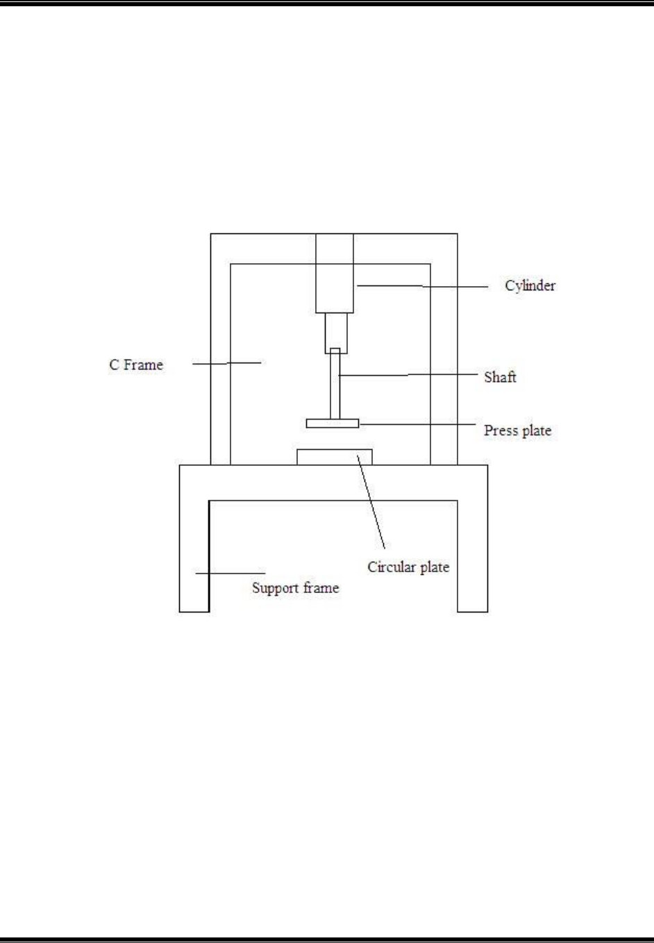
PNEUMATIC STAMPING MACHINE
Department of mechanical engineering-ATME mysore Page12
Piston
Circular plate
Base support
Bearing blocks
Fig 1.1 Schematic Diagram OfPneumatic Stamping Machine.
The compressed air from the compressor at the pressure of 8 to 10bar is passed through a pipe
connected to the direction control valve with one input. Due to the high air pressure at the bottom
of the piston, the air pressure below the piston is more than the pressure above the piston. This
moves the piston rod upwards which further moves up the effort arm, pivoted by control unit.
This force acting is passed on to press platewhich also moves downwards. The press plate is
guided by a guide which is fixed such that the press plate is clearly guided to the circular plate.

PNEUMATIC STAMPING MACHINE
Department of mechanical engineering-ATME mysore Page13
The materials are in between the press plate and circular plate. So as the press plate descends
down, the material is stamped to the required metal plate and required impression is obtained.
1.6 Pneumatic System
Pneumatic systems use pressurized gases to transmit and control power. As the name
implies, pneumatic system typically use air (rather than some other gas) as the fluid medium
because air is safe, low cost and readily available fluid. It is particularly safe inn environments
where an electrical spark could ignite leaks from system components (Majumdar, 1995).There
are several reasons for considering the use of pneumatic systems instead of hydraulic systems.
Liquids exhibit greater inertia than do gases. Therefore, in hydraulic systems the oil is a potential
problem when accelerating and decelerating actuators and when suddenly opening and closing
valves. Liquids also exhibit greater viscosity than do gases.
This results in larger frictional pressure and power losses. Also, since hydraulic system
use a fluid foreign to the atmosphere, they require special reservoirs and no leak- system designs.
Pneumatic systems use air that is exhausted directly back into the surrounding environment.
Generally speaking, pneumatic systems are less expensive than hydraulic systems (Majumdar,
1995).
However, because of the compressibility of air, it is impossible to obtain precise,
controlled actuator velocities with pneumatic systems. Also, precise positioning control is not
obtainable. In applications where actuator travel is to be smooth and steady against a variable
load, the air exhaust from the actuator is normally metered. Whereas pneumatic pressures are
quite low to explosion dangers involved if components such as air tanks should rupture(less than
250psi), hydraulic pressure can be as high as 12000psi. Thus hydraulic pressure can be high-
power systems whereas pneumatics is confined to low power application (Majumdar, 1995).
1.7 Principles and Maintenance
The technology of pneumatics has gained tremendous importance in the field of work
place rationalization and automation from old fashioned timber works and coal mines modern
machine shops and space robots. Certain characteristics of compressed air have made this
medium quite suitable for use in modern manufacturing and production plants. It is therefore,
important that technicians and engineers should have a good working knowledge of pneumatic

PNEUMATIC STAMPING MACHINE
Department of mechanical engineering-ATME mysore Page14
system, air operated tools and other accessories, including a thorough and clear concept of the
physical principles that govern the behavior of compressed air (Majumdar, 1995).
1.8 Application of Pneumatic
With the introduction of pneumatics in the manufacturing process, the industry is
benefited with a cheaper medium of industrial automation which s judiciously used, may bring
down the cost of production to a much lower level. A few decades ago, maximum application of
pneumatics was probably in the field of construction where main source of power for tools like
power hammer drills and etc was compressed air only. Now, compressed air is used in every
walk of industrial life starting with pneumatic cranes to the use of air in the brake systems and so
on.
1.9 Advantages of pneumatic system
1. Wide availability of air.
2. Compressibility of air
3. Easy transportability of compressed air in pressure vessels, containers and in long pipes
4. Fire proof characteristic of the medium
5. Simple construction of pneumatic elements and easy handling
6. High degree of controllability of pressure, speed, and force
7. Possibility of easy but reasonably reliable remote controlling
8. Easier maintenance
Compared to hydraulic system, pneumatic system has better operational advantages but it cannot
replace hydraulic system so far as power requirement and accuracy of operations are concerned.
In areas of hazards, probably air will be a better medium of power than electrical system,
hydraulic system and steam power system. It may not be necessary at this stage to dwell further
on the multitude of advantages that may be derived from applying pneumatic energy on
production plants and systems except what has been already mentioned earlier (Maunder, 1995).
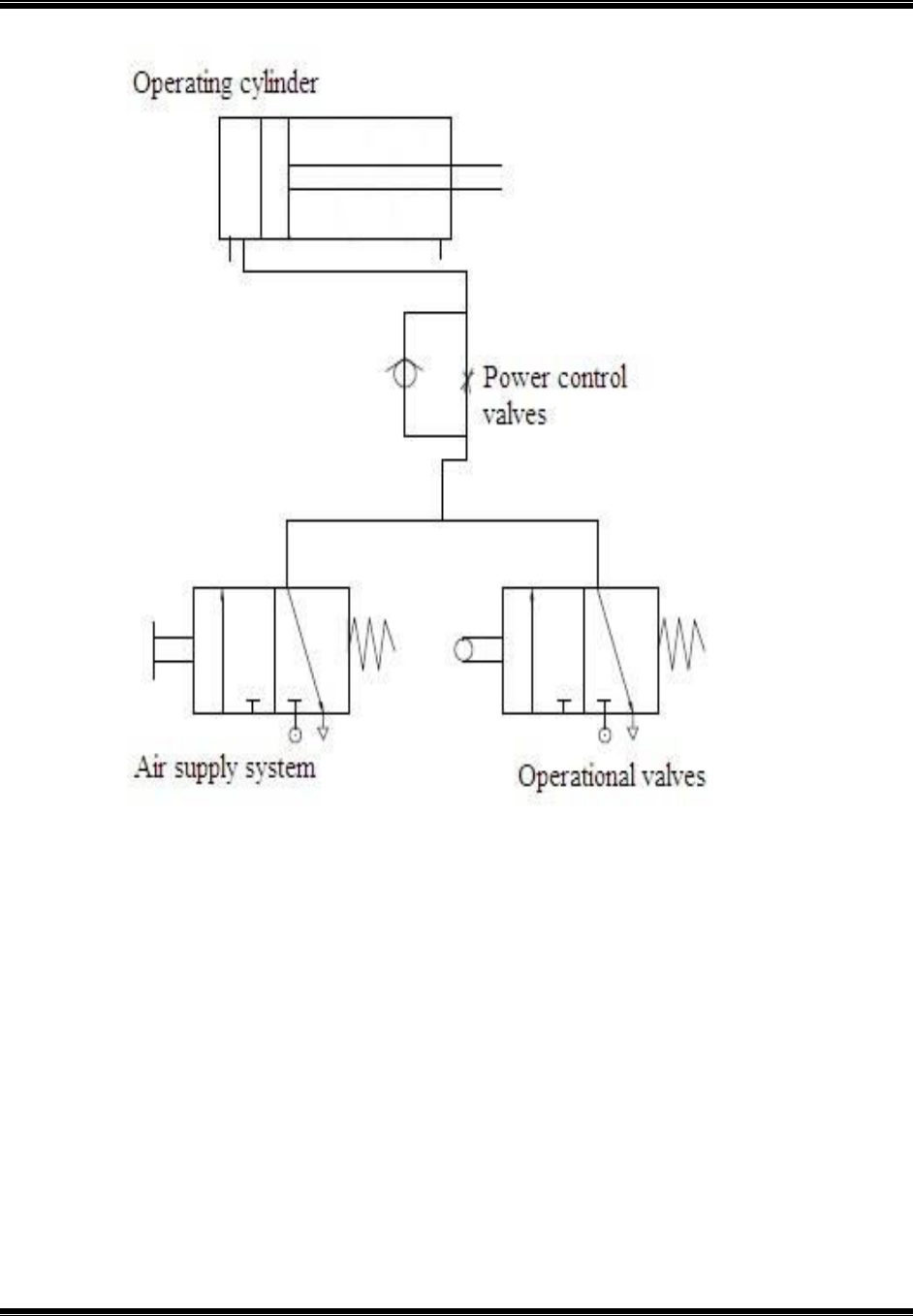
1.10 Area of application of pneumatic system
Damp Hopper

PNEUMATIC STAMPING MACHINE
Department of mechanical engineering-ATME mysore Page15
Stamping
Mining (Door opening & closing)
Material flow
Automobile (Braking System, engine etc.)
Tools (Jackhammer, drills etc.)
Punching
Motion Restriction in CNC machines
Dental Care
Pneumatic gun for bolt tightening
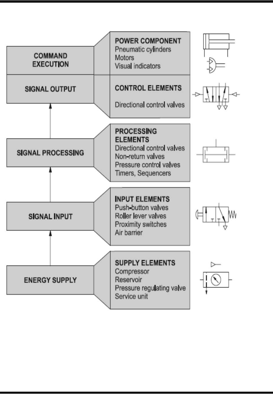
PNEUMATIC STAMPING MACHINE
Department of mechanical engineering-ATME mysore Page16
Fig 1.2SchematicDiagramOfPneumaticControlSystem.

PNEUMATIC STAMPING MACHINE
Department of mechanical engineering-ATME mysore Page17
Chapter 2
Literature Survey
P.Goyal, “Review on Pneumatic Punching Machine and Modification in Punch Tool to
Reduce Punching Force Requirement”, ISSN 2394 – 3386, Volume 2, Issue 2, February
2015
This project work deals with the design of pneumatically controlled small scale punching
machine to carry out piercing operation on thin sheets (1-2 mm) of different material (aluminium
and plastic). Reduction in punching force requirement being the main aim of this project work is
obtained by modification in punch tool design i.e. by provision of shear on punch face.
Subsequently it results in reduction in amount of punching force requirement. And further a
CATIA model of the machine is developed on the basis of calculations with respect to punching
force requirement.
A.S. AdityaPolapragada et al, “Pneumatic Auto Feed Punching and Riveting Machine”,
Vol. 1 Issue 7, September - 2012
The pneumatic system has gained a large amount of importance in last few decades. This
importance is due to its accuracy and cost. This convenience in operating the pneumatic system
has made us to design and fabricate this unit as our project. This unit, as we hope that it can be
operated easily with semi-skilled operators.
The pneumatic press tool has an advantage of working in low pressure, that is even a pressure of
6 bar is enough for operating the unit. The pressurized air passing through the tubes to the
cylinder, forces the piston out whose power through the linkage is transmitted to the punch. The
work piece thus got is for required dimensions and the piece can be collected through the land
clearance provided in the die. The die used in this is fixed such that the die of required shape can
be used according to the requirement. This enables us to use different type punch dies resulting
in a wide range of products. Different types of punch as requirement can be thus got. According
to the work material the operating pressure can be varied.

PNEUMATIC STAMPING MACHINE
Department of mechanical engineering-ATME mysore Page18
GauravPradipSonawane, “Design, Analysis and Manufacturing of Hydro-pneumatic Press
Machine”, Vol, 04 || Issue, 11 || November– 2014
A Hydro-pneumatic press is a press machine utilizing both air and oil in its operation and gives
higher outlet hydraulic pressure with lower inlet pneumatic pressure. In this project the press is
design and manufacture for pressing sleeve bearing into the circular casting part. Casting part is
thick cylinder and sleeve bearing is kind of cylindrical bearing. Two actuators are used in the
press one is for vertical pressing and other is for horizontal pressing. This paper includes the
concept development, design, analysis and manufacturing of press machine. Various parts of the
press are modelled by using Pro-E modelling software. Structural analysis has been applied on
the parts of press machine by using analyzing software ANSYS.
ArunS etal, “Automatic Punching Machine: A Low Cost Approach”, Volume 4, Number 5
(2014).
The proposed work describes the design and fabrication of prototype of automatic punching
machine controlled by PLC and shedding light on the working principle and the hardware
structure of the system. Punching or pressing process is one of the most important and necessary
processing step in sheet metal industry. By automating this process one can have a greater
control over the process. Programmable Logic Controllers are used for the control of the system.
This system can replace existing manual feed and operated punching and pressing machines. By
interfacing PLC controls with the conventional machines, it is possible to achieve good results in
the form of reduced manufacturing lead time, reduced cost and increased safety of the worker.
Rakshith M N et al, “Design And Fabrication of Pneumatically Operated
Embossing Machine With Programmable Controller” , Volume-1, Issue-2, 2013
In manual operated embossing machine, hand operated lever is used emboss on workpiece.
Embossing work depends on operator i.e. productivity depends on operator efficiency. In manual
operated embossing machine operator perform operations like loading workpiece to work holder,
operating hand lever to perform embossing, checking whether emboss is performed perfectly,
unloading of workpiece and counting of finished workpiece. Thus the loading ofworkpeice, to
operate hand lever and unloading of workpeicewill take more cycle time. This leads to increase

PNEUMATIC STAMPING MACHINE
Department of mechanical engineering-ATME mysore Page19
in manufacturing lead time (MLT) and work in process (WIP). The main limitation of manual
operations is it is tedious and less productivity. In fast replication process where mass production
requires continuous operation, manual operated embossing machine does not suits hence
innovation requires to enhance fast replication continuous mass production.To overcome this
problem in manual operated embossing machine, the concept of automation is used. This project
involves design and fabrication of pneumatically operated embossing machine with PLC. In this
machine operations like loading workpiece to work holder, embossingand unloading of
workpiece are performed automatically.
Mr. Ravipotha et al, “Automatic Pneumatic Stamping Machine”,ISSN No: 2348-4845
The pneumatic system has gained a large amount of importance in last few decades. This
importance is due to its accuracy and cost. It can be operated easily with semi-skilled operators
.This convenience in operating the pneumatic system has made us to design and fabricate this
unit which is operated by pneumatics as our project. The project is further elaborated to the
function of pneumatics with their behavior in several aspects. This machine has an advantage of
working even at low pressures, that is even pressure of 6 bars is enough for the operation. The
pressurized air passing through the cylinder, forces the piston out whose power through linkages
is transmitted to the work piece. The work piece thus got it for the required dimensions and the
impression is made on it.
The stamping machine uses a mechanism of quick retrieval done by acting of pressurized air
inside of it. The operation of the compressed air is done by using a solenoid valves. This project
also elaborates about the other applications just by changing its arm.
PNEUMATIC STAMPING MACHINE
Department of mechanical engineering-ATME mysore Page20
Chapter 3
Component Details
Pneumatic stamping machine consists of following components.
Pneumatic circuit
Air compressor
Direction control valves
Pressure relief valves
Flexible hoses
3.1 Pneumatic system
Pneumatic execution components provide rectilinear or rotary movement. Examples of
pneumatic execution components include cylinder pistons, pneumatic motors, etc. Rectilinear
motion is produced by cylinder pistons, while pneumatic motors provide continuous rotations.
There are many kinds of cylinders, such as single acting cylinders and double acting cylinders.
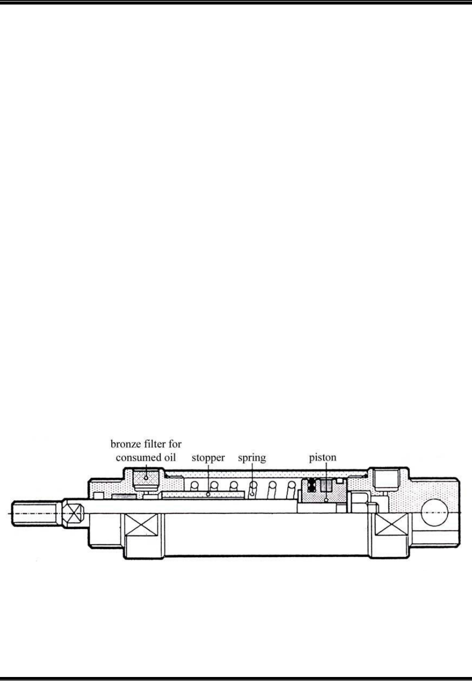
(i) Single acting cylinder
A single acting cylinder has only one entrance that allows compressed air to flow through.
Therefore, it can only produce thrust in one direction. The piston rod is propelled in the opposite
direction by an internal spring, or by the external force provided by mechanical movement or
weight of a load (Fig 3.1).
Fig. 3.1 CrossSection Of a Single Acting Cylinder
PNEUMATIC STAMPING MACHINE
Department of mechanical engineering-ATME mysore Page21
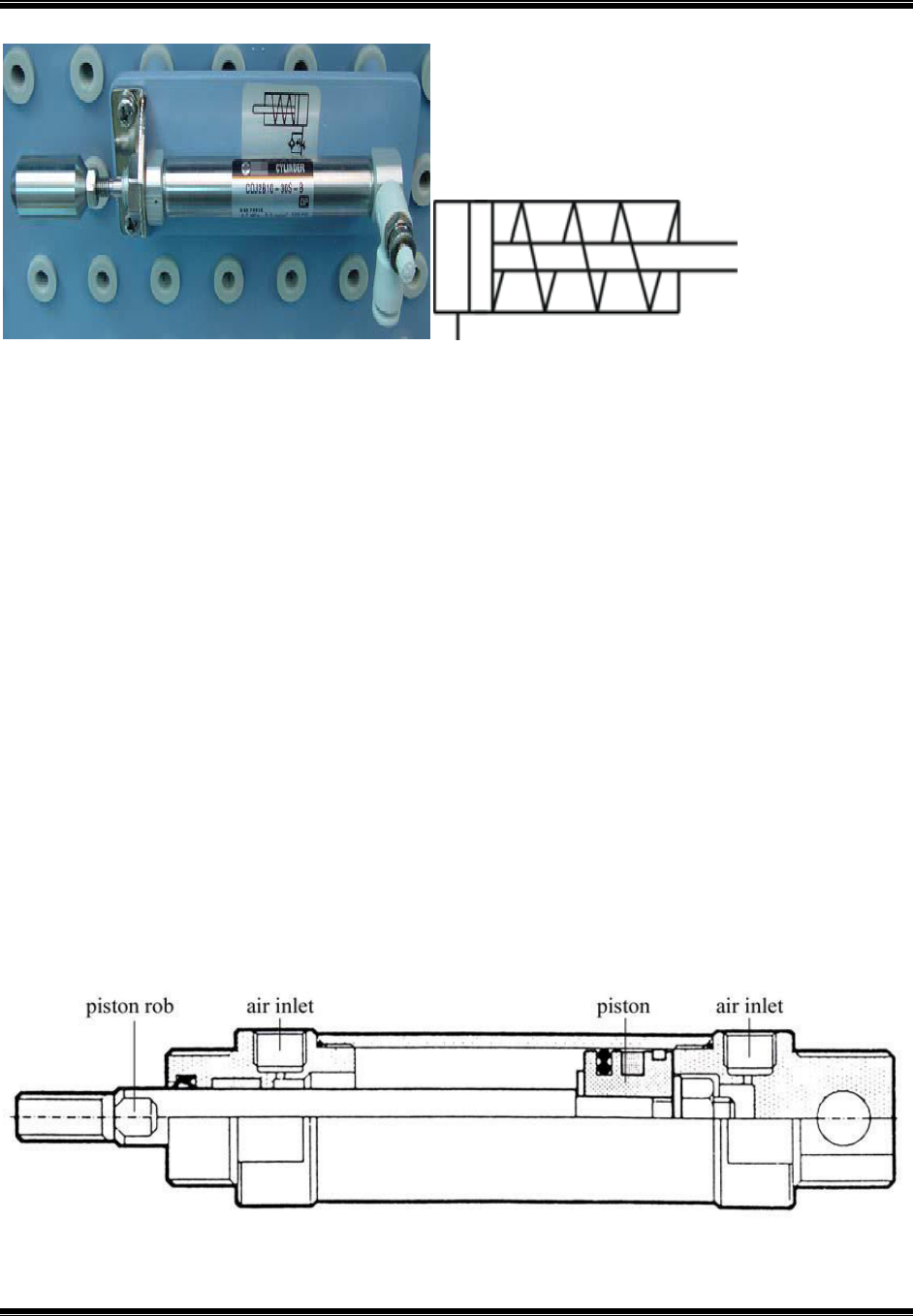
Fig. 3.2(a) Single Acting Cylinder Fig 3.2(b) Pneumatic Symbol Of A Single
Acting Cylinder
The thrust from the piston rod is greatly lowered because it has to overcome the force from the
spring. Therefore, in order to provide the driving force for machines, the diameter of the cylinder
should be increased. In order to match the length of the spring, the length of the cylinder should
also be increased, thus limiting the length of the path. Single acting cylinders are used in
stamping, printing, moving materials etc.
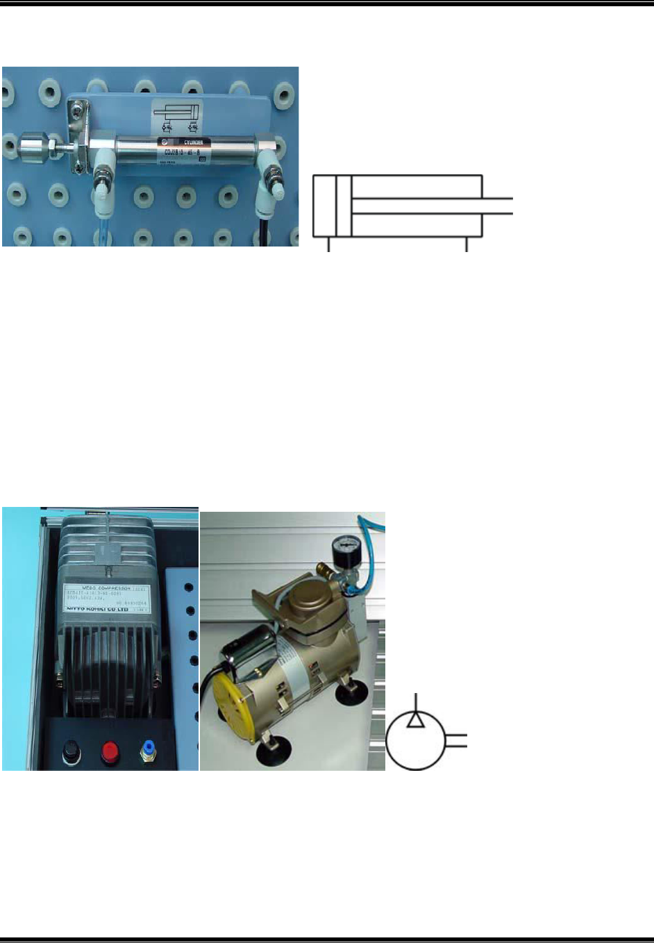
(ii) Double acting cylinder
In a double acting cylinder, air pressure is applied alternately to the relative surface of thepiston,
producing a propelling force and a retracting force (Fig. 3.3). As the effective area of thepiston is
small, the thrust produced during retraction is relatively weak. The impeccable tubes ofdouble
acting cylinders are usually made of steel. The working surfaces are also polished andcoated
with chromium to reduce friction.
Fig. 3.3 Cross Section Of A Double Acting Cylinder
PNEUMATIC STAMPING MACHINE
Department of mechanical engineering-ATME mysore Page22
Fig. 3.4 (a) DoubleActing Cylinder Fig.3.4 (b) Symbol Of Double Acting Cylinder
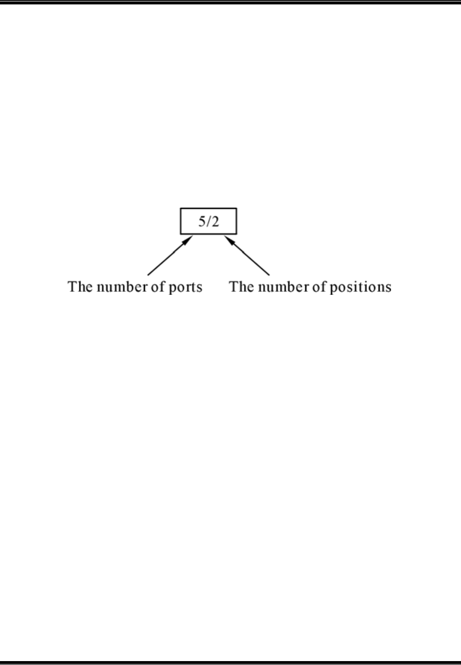
3.2 Compressor
A compressor can compress air to the required pressures. It can convert the mechanical energy
from motors and engines into the potential energy in compressed air (Fig. 2). A single central
compressor can supply various pneumatic components with compressed air, which is transported
through pipes from the cylinder to the pneumatic components. Compressors can be divided into
two classes: reciprocatory and rotary.
Fig 3.5
(a) Compressor Used In Schools (b) Compressor Used In (c) Pneumatic Symbol Of
Laboratoriesa Compressor
PNEUMATIC STAMPING MACHINE
Department of mechanical engineering-ATME mysore Page23
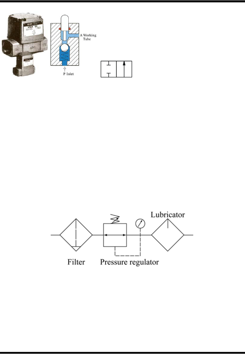
3.3 Directional control valve
Directional control valves ensure the flow of air between air ports by opening, closing and
switching their internal connections. Their classification is determined by the number of ports,
the number of switching positions, the normal position of the valve and its method of operation.
Common types of directional control valves include 2/2, 3/2, 5/2, etc. The first number
represents the number of ports; the second number represents the number of positions. A
directional control valve that has two ports and five positions can be represented by the drawing
in Fig. 8, as well as its own unique pneumatic symbol.
Fig.3.6 DescribingA 5/2 Directional Control Valve
(i) 2/2 Directional control valve
The structure of a 2/2 directional control valve is very simple. It uses the thrust from the spring
to open and close the valve, stopping compressed air from flowing towards working tube ‘A’
from air inlet ‘P’. When a force is applied to the control axis, the valve will be pushed open,
connecting ‘P’ with ‘A’ (Fig. 9). The force applied to the control axis has to overcome both air
pressure and the repulsive force of the spring. The control valve can be driven manually or
mechanically, and restored to its original position by the spring.
PNEUMATIC STAMPING MACHINE
Department of mechanical engineering-ATME mysore Page24
Fig. 3.7 (a) 2/2 Directional Control Valve (b) Cross Section (c) Pneumatic Symbol Of a
2/2 Directional Control Valve
3.4 Pressure regulating component
Pressure regulating components are formed by various components, each of which has its own
pneumatic symbol:
(i) Filter – can remove impurities from compressed air before it is fed to the pneumatic
components.
(ii) Pressure regulator – to stabilize the pressure and regulate the operation of pneumatic
components
(iii) Lubricator – To provide lubrication for pneumatic components
Fig 3.8 Pneumatic Symbols Of The Pneumatic Components Within A Pressure Regulating
Component

PNEUMATIC STAMPING MACHINE
Department of mechanical engineering-ATME mysore Page25
Chapter 4
Detail Design
4.1 Design Calculations
• Pressing force: - The force which has to act on the stock material in order to Stamp the sheet.
• Pressing force = L x t x T
max
= 50 x 1 x 180 = 9000N
• L= Length of periphery to be stamped in mm = 50mm
• t= Sheet thickness in mm =1mm
• T
max
= Shear strength in N/mm
2
= 180 N/mm
2
Press force, F
p
= 9000N
Aluminum sheet dimension = 150 x 75mm
Area = 150 x 75 = 11250mm
2
Total length of cut
(L) in mm
50
50
50
50
50
50
Al sheet thickness
(t) in mm
1
1.1
1.2
1.3
1.4
1.5
T
max
of Aluminium
in N/mm
2
180
180
180
180
180
180
Press force (N)
9000
9900
10800
11700
12600
13500
Impact stress
(N/mm
2
)
0.8
0.88
0.96
1.04
1.12
1.2
Table 4.1 Press Force Calculations ForAluminum Sheet Of Different Thickness

PNEUMATIC STAMPING MACHINE
Department of mechanical engineering-ATME mysore Page26
4.2 Punch Design
Force required is reduced which can be seen by the formula,
Where,
F= Reduced Force after providing shear in Newton (N)
F
max
= Maximum force required to punch the sheet of thickness t in Newton (N)
K= Percentage Penetration
t = Thickness of sheet in mm
I= Amount of shear given to the tool (in terms of t) in mm
Aluminum Sheet
1) For I=t/5 & K=0.6
F=0.75F
max
2) For I=t/4 & K=0.6
F=0.705F
max
3) For I=t/3 & K=0.6
F=0.643F
max
4) For I=t/2 & K=0.6
F=0.545F
max
5) For I=t/1 & K=0.6
F=0.375F
max

PNEUMATIC STAMPING MACHINE
Department of mechanical engineering-ATME mysore Page27
Amount of
Shear (I)
in mm
t/5
t/4
t/3
t/2
t
Maximum
Force
required(F
max
)
in N
9000
9000
9000
9000
9000
Force (F
max
)
after
providing shear
in N
6750
6345
5787
4905
3375
Percentage
reduction in
Force required
25
29.5
35.7
45.5
62.5
Table 4.2 Percentage Reduction Calculations After Providing Shear On Tool For
AluminumSheet
4.3 Designing of cylinder
Force required = 6750 N
Working pressure = 10 bar = 1Mpa
To find the Bore diameter of the cylinder we use the following formula
• According to the formula bore diameter of the cylinder is D= 93.05 mm
• As per the standards bore diameter, D = 95 mm
According to the bore diameter,
• Piston rod diameter is, d = 0.3(D) = 28 mm
• Stroke length = 200 mm
PNEUMATIC STAMPING MACHINE
Department of mechanical engineering-ATME mysore Page28
4.1 Pneumatic Circuit Diagram
PNEUMATIC STAMPING MACHINE
Department of mechanical engineering-ATME mysore Page29
4.4 Part Drawings and Assembly
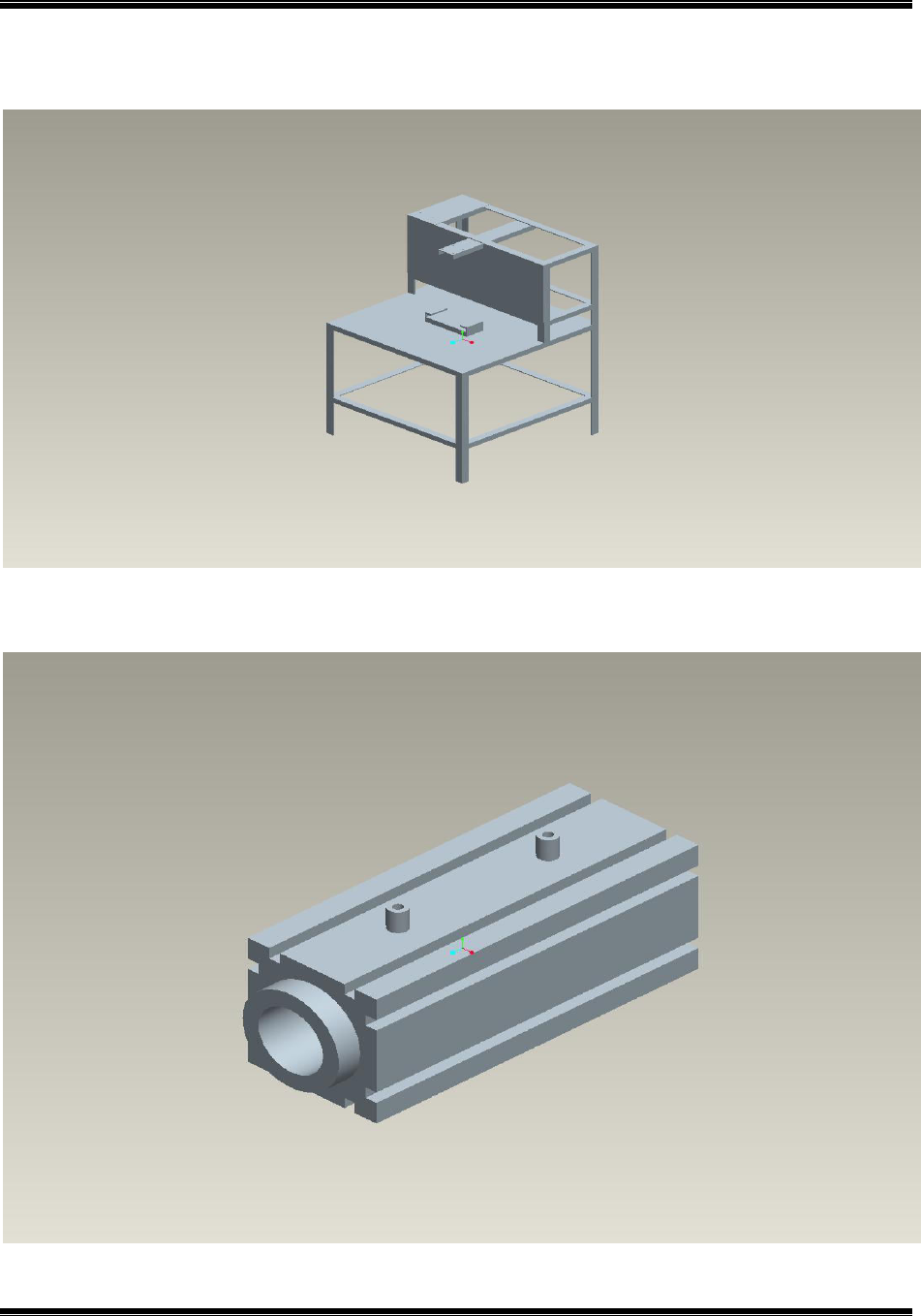
Fig 4.2 C Frame
Fig 4.3 Pneumatic Cylinder
PNEUMATIC STAMPING MACHINE
Department of mechanical engineering-ATME mysore Page30
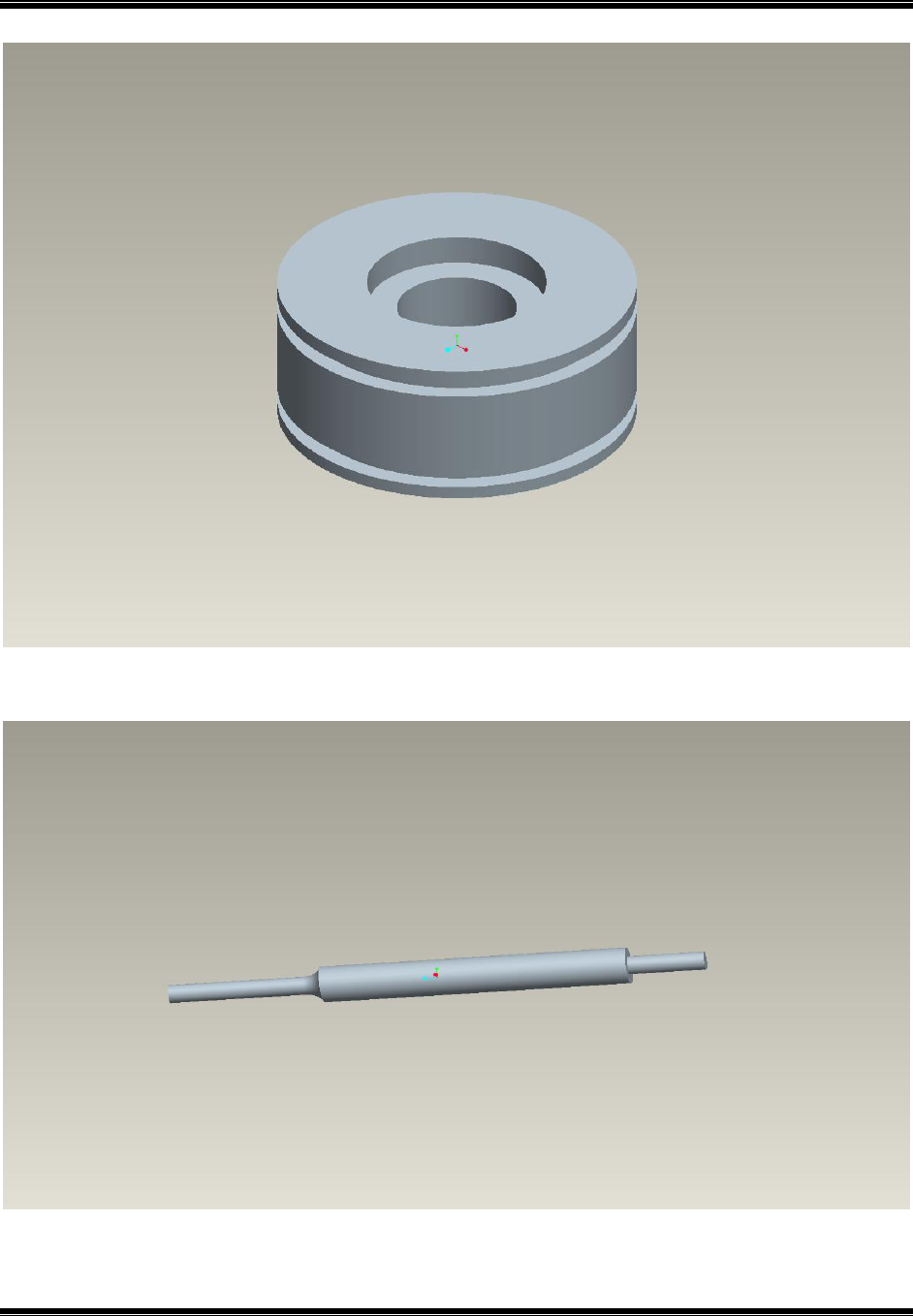
Fig 4.4 Piston
Fig 4.5 Connecting Rod
PNEUMATIC STAMPING MACHINE
Department of mechanical engineering-ATME mysore Page31
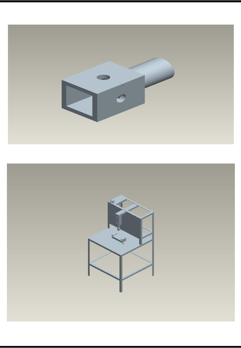
Fig 4.6 Punch
Fig 4.7 Pneumatic Stamping Machine Assembly

PNEUMATIC STAMPING MACHINE
Department of mechanical engineering-ATME mysore Page32
Chapter 5
Fabrication
Fabrication is the process of building machine, structures and other equipment’s by deploying
various process and operations like cutting, forming, setup, full welding and assembling
components made from raw material. A brief description of selection of raw material is given
below.
Material details
In this project, different materials for different elements are used in building a pedal operated can
crusher, the selection of appropriate material for the respective components was based on many
parameters such as,
Machinability
Material strength
Weight
Cost of the material
5.1 Supporting Frames
5.11 C Frame
There are two support frames. One of them is C frame through which pneumatic piston and
cylinder are mounted. Another one is rectangular frame. On which C frame and rectangular
frame is mounted.
Fig 5.1 C-Frame
PNEUMATIC STAMPING MACHINE
Department of mechanical engineering-ATME mysore Page33
Fig 5.2(a) C- Frame
Features
Data
Length
500mm
Breadth
650mm
Thickness
250mm
Material
Mild Steel
Quantity
1
Nature of operation
Cutting and Welding
Table 5.1 Features of C-Frame
PNEUMATIC STAMPING MACHINE
Department of mechanical engineering-ATME mysore Page34
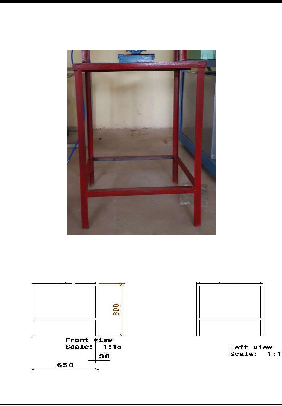
5.12 Base Frame
Fig.5.3 Base Frame
Fig 5.3(a) Base Frame
PNEUMATIC STAMPING MACHINE
Department of mechanical engineering-ATME mysore Page35
Features
Data
Length
600mm
Breadth
650mm
Thickness
30mm
Material
Mild Steel
Quantity
1
Nature of operation
Cutting and Welding
Table 5.2 Features of Base Frame
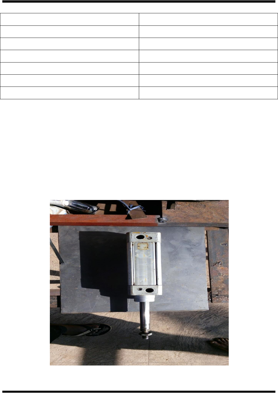
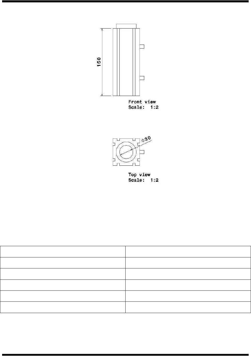
5.2 Pneumatic cylinder
Pneumatic cylinder is mounted vertically through the C Frame. It is connected to the compressor
through hose pipes.
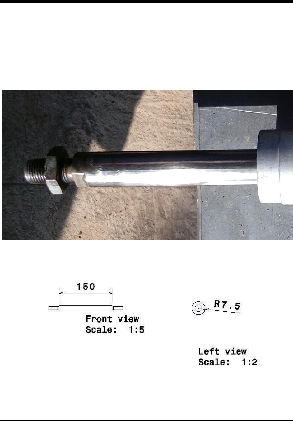
Fig 5.4 Pneumatic Cylinder
PNEUMATIC STAMPING MACHINE
Department of mechanical engineering-ATME mysore Page36
Fig 5.4(a) Pneumatic Cylinder
Table 5.3 Features OfPneumatic Cylinder
Features
Data
Length
150mm
Diameter
30mm
Material
Mild steel
Quantity
1
Nature of operation
Casting, drilling and grinding
PNEUMATIC STAMPING MACHINE
Department of mechanical engineering-ATME mysore Page37
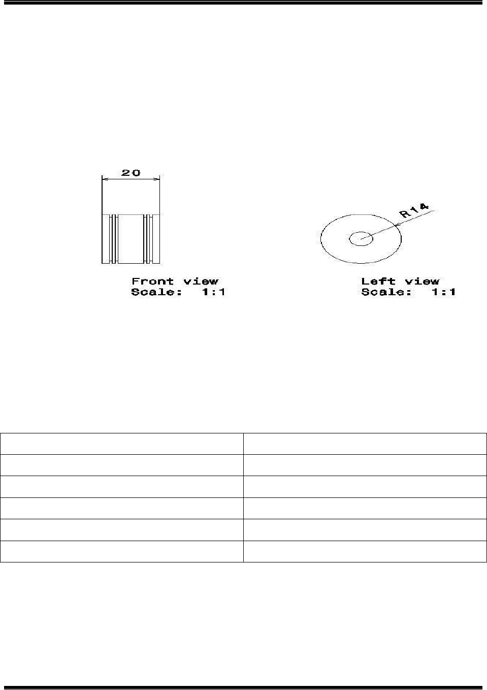
5.3 Piston
The piston is connected to the connecting rod. The hydraulic oil pressure pushes the piston
downward.
Fig5.5 Piston
Features
Data
Length
20mm
Diameter
28mm
Material
Mild Steel
Quantity
1
Nature of operation
Casting, Drilling.
Table 5.4 Features of Piston
PNEUMATIC STAMPING MACHINE
Department of mechanical engineering-ATME mysore Page38
5.4 Connecting Rod
The connecting rod is fixed to the press plate. It is made up of Mild steel.
Fig 5.6 Connecting Rod
PNEUMATIC STAMPING MACHINE
Department of mechanical engineering-ATME mysore Page39
Features
Data
Length
150mm
Diameter
15mm
Material
Mild steel
Quantity
1
Nature of operation
Cutting, welding
Table 5.5 Features of Connecting Rod
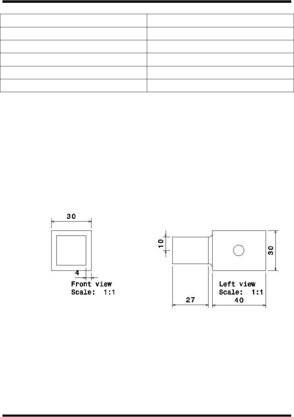
5.5 Punch Holder
The punch holder holds the punch machine and consists of number punches.
Fig5.7 Punch Holder

PNEUMATIC STAMPING MACHINE
Department of mechanical engineering-ATME mysore Page40
Features
Data
Length
40mm
Breadth
30mm
Thickness
4mm
Material
Mild steel
Quantity
1
Nature of operation
Casting, cutting and welding
Table 5.6 Features of Punch Holder
5.6 Direction control valve
A flow control valve regulates the flow or pressure of a fluid. Control valves normally respond
to signals generated by independent devices such as flow meters or temperature gauges.
Fig 5.8 Direction Control Valve
PNEUMATIC STAMPING MACHINE
Department of mechanical engineering-ATME mysore Page41
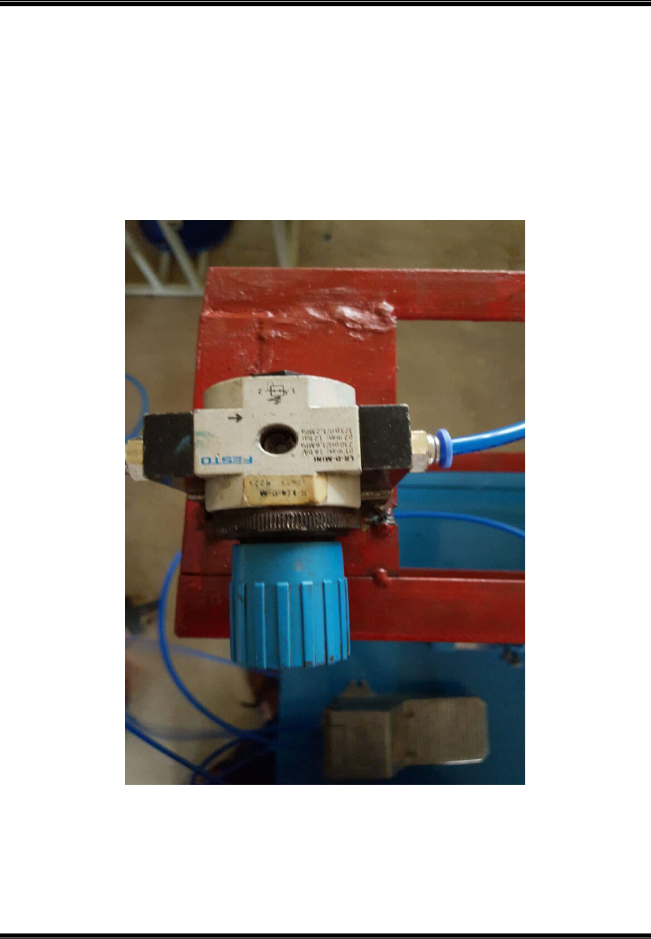
5.7 Pressure Regulating Valve
A pressure regulator is a valve that automatically cuts off the flow of a liquid or gas at a certain
pressure. Regulators are used to allow high-pressure fluid supply lines or tanks to be reduced to
safe and/or usable pressures for various applications.
Fig 5.9Pressure Regulating Valve
PNEUMATIC STAMPING MACHINE
Department of mechanical engineering-ATME mysore Page42
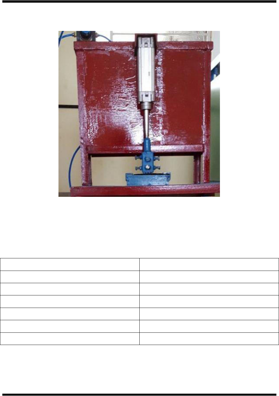
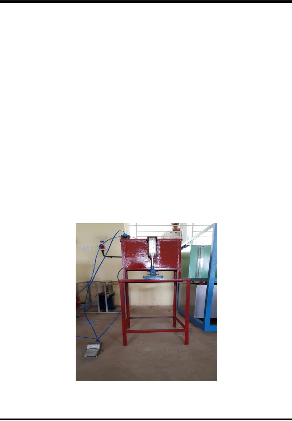
5.8Assembly
Assembly is the process of assembling individual components together to become a working
module. Assemblies consist of various parts, from machined parts to commercial standard parts
such as screws, nuts and pins. It may also include plastic, metal or a variety of other materials.
The processes of combining the components may include mechanical torque, brazing, welding or
a variety of other possible processes.
After all the components are prepared according to the drawings provided to the operator all the
components are assembled in the following sequence.
The C Frame and Rectangular frame are fixed by welding.
The pneumatic cylinder is mounted through the C frame vertically.
The piston is connected to the connecting rod which is in turn connected to the press plate
or punch.
A base plate is mounted on the rectangular frame.
An air compressor is connected to pneumatic cylinder which through flexible hoses.
Fig5.10 Assembly

PNEUMATIC STAMPING MACHINE
Department of mechanical engineering-ATME mysore Page43
Chapter 6
Project Cost
Sl no
Component
Quantity
Cost
1
Angular
4
600
2
C Channel
2
500
3
Pressure regulating valve
1
600
4
Pneumatic cylinder
1
2500
5
Leg operated valve
1
400
6
Punch
1
500
7
Quick connector
4
200
8
Hose pipes
3
100
Total Cost
5400
Table 6.1 Project Cost
Labor cost = Rs.1500/-
Total cost = Fabrication cost + Labor cost = 5400 + 1500 = Rs. 6900/-

PNEUMATIC STAMPING MACHINE
Department of mechanical engineering-ATME mysore Page44
CONCLUSION
The general purpose of the present invention, which will be described subsequently in greater
details, is to provide a portable pneumatic stamping ma-chine which has many advantages of the
low power consumption and effective performance and many specified features of the system
which is not anticipated The further objective of the system is, this is susceptible of a low cost of
manufacturing with regards to both cost and labor, and which accordingly is then susceptible of
low prices of sale to the public, so thereby making such stamping machine are very economically
to available to the public.

PNEUMATIC STAMPING MACHINE
Department of mechanical engineering-ATME mysore Page45
References
[1] P.M.Pradhan, “Experimental Investigation and Fabrication of Pneumatic Punch”,
International Journal ofInnovative Research in Science, Engineering and Technology, Vol. 2,
Issue 6, June 2013.
[2] A.S. AdityaPolapragada& K. Sri Varsha, “Pneumatic Auto Feed Punching and Riveting
Machine “, International Journal of Engineering Research & Technology (IJERT) Vol. 1 Issue 7,
September - 2012 ISSN: 2278-0181.
[3] U.P. Singh, “Design Study of the Geometry of a Punching tool”, Journal of Materials
Processing Technology, 33 (1992) 331-345 Elsevier.
[4] P.C.Sharma, “Methods of reducing Cutting Forces”, Pages 63-66, Production Engineering,
Ninth edition, 2004, S. Chand & Company Ltd.
[5] E. Paul. Degarmo, “Shearing in Metal Cutting”, Pages 518-528, Materials and Processes in
Manufacturing, Eighth edition, 2003, Prentice Hall of India Pvt Ltd.
[6]P.Goyal, “Review on Pneumatic Punching Machine and Modification in Punch Tool to
Reduce Punching Force Requirement”, ISSN 2394 – 3386, Volume 2, Issue 2, February 2015
[7]A.S. AdityaPolapragada et al, “Pneumatic Auto Feed Punching and Riveting Machine”, Vol.
1 Issue 7, September - 2012
[8] GauravPradipSonawane, “Design, Analysis and Manufacturing of Hydro-pneumatic Press
Machine”, Vol, 04 || Issue, 11 || November– 2014
[9]ArunS et al, “Automatic Punching Machine: A Low Cost Approach”, Volume 4, Number 5
(2014).
[10] K. Mahadevan, Design Data Handbook, Third edition, Reprint 2002, CBS Publishers &
distributors.
