
I
DESIGN AND FABRICATION OF AUTOFEED PNEUMATIC
PUNCHING AND RIVETING MACHINE
Submitted in partial fulfilment of the requirements
for the award of
Bachelor of Engineering degree in Mechanical Engineering
by
Velayutham.Pon (37150221)
Tison Antonio.J (37150196)
DEPARTMENT OF MECHANICAL ENGINEERING
SCHOOL OF MECHANICAL ENGINEERING
SATHYABAMA
INSTITUTE OF SCIENCE AND TECHNOLOGY
(DEEMED TO BE UNIVERSITY)
Accredited with Grade “A” by NAAC I 12B Status by UGC I Approved by AICTE
JEPPIAAR NAGAR, RAJIV GANDHI SALAI,
CHENNAI - 600 119
APRIL 2021

II
SATHYABAMA
INSTITUTE OF SCIENCE AND TECHNOLOGY
(DEEMED TO BE UNIVERSITY)
Accredited with “A” grade by NAAC I 12B Status by UGC I Approved by AICTE
Jeppiaar Nagar, Rajiv Gandhi Salai, Chennai – 600 119
www.sathyabama.ac.in
DEPARTMENT OF MECHANICAL ENGINEERING
BONAFIDE CERTIFICATE
This is to certify that this Project Report is the bonafide work of Velayutham.pon
(37150221), TisonAntonio.J (37150196) who carried out the project entitled
“DESIGN AND FABRICATION OF AUTOFEED PNEUMATIC PUNCHING AND
RIVETING MACHINE”, under our supervision from November 2020 to April 2021
Internal Guide
Dr.G.Arunkumar, M.E., Ph.D
Head of the department
Dr.G.Arunkumar, M.E., Ph.D
Submitted for Viva voce Examination held on APRIL 2021
Internal Examiner
External Examiner
III
DECLARATION
We Velaythum.pon (37150221) , TisonAntonio (37150196) hereby declare that the
project Retort entitled “DESIGN AND FABRICATION OF AUTOFEED PNEUMATIC
PUNCHING AND RIVETING MACHINE” done by me under the guidance of
Dr.G.Arunkumar, M.E., Ph.D., is submitted in partial fulfilment of requirements for
the award of Bachelor of Engineering degree in Mechanical Engineering.
DATE: SIGNATURE OF THE CANDIDATE
PLACE: CHENNAI
IV
ACKNOWLEDGEMENT
I am pleased to acknowledge my sincere thanks to Board of Management of
SATHYABAMA for their kind encouragement in doing this project and for completing
it successfully. I am grateful to them.
I convey my thanks to Dr.S. Prakash, M.E., Ph.D., Dean, School of Mechanical
Engineering and Dr.G. Arunkumar, M.E., Ph.D., Head of the Department, Dept. of
Mechanical Engineering for providing me necessary support and details at the right
time during the progressive reviews.
I would like to express my sincere and deep sense of gratitude to my Project Guide
Dr. G. Arunkumar, M.E., Ph.D., for his valuable guidance, suggestions and
constant encouragement paved way for the successful completion of my project
work.
I wish to express my thanks to all Teaching and Non-teaching staff members of the
Department of Mechanical Engineering who were helpful in many ways for the
completion of the project.
V
ABSTRACT
Metal in the form of sheets is more important. But metal in the form of sheets cannot
be directly used, operations like punching, blanking, bending, riveting, etc. are need
to be carried out on the metal sheets. For these operations, most large-scale
manufacturing industries use hydraulically operated machines which are not cost-
effective, most small and medium scale industries use hand-operated machines for
carrying out sheet metal operation which are slow. The pneumatic punching and
riveting machine are capable of working in low pressure that is even a pressure of 6
bar is enough. The pressurized air is passing through the tubes to the cylinder forces
the piston out which in turn actuates the piston down which in turn does the process
of punching or rivet. This enables us to use different types of tool to perform different
operations. After the completion of punch or rivet in the sheet metal the pressurized
air flows to the bottom of the cylinder which actuates the piston upwards so the metal
is freed from the tool and the next punch or rivet process is made available. According
to the working material the working pressure can be changed. This enables us to use
different types of punch or rivet tool dies resulting in a wide range of products
VI
TABLE OF CONTENT
CHAPTER TITLE PAGENO.
ABSTRACT V
LIST OF FIGURES VIII
LIST OF TABLES IX
1 INTRODUCTION 1
1.1 PUNCHING AND RIVETING 1
1.2 NEED FOR AUTOMATION 3
1.3 SELECTION OF PNEUMATICS 5
1.4 COMPRESSED AIR 7
2 LITERATURE SURVEY 8
3 AIM AND SCOPE 13
4 MATERIALS AND WORKING PRINCIPLE 14
4.1 PNEUMATIC CYLINDER 14
4.1.1 Single-acting Cylinder 14
4.1.2 Double-acting Cylinder 15
4.1.3 Advantages of Double-acting Cylinder 15
4.2 COMPRESSOR 18
4.3 5/2 DIRECTIONAL FLOW CONTROL VALUE 21
4.3.1 Parts of 5/2 Solenoid Valve 23
4.4 DC Motor 25
4.4.1 Advantages of DC Motor 27
4.5 Pneumatic Hose Pipes 28
4.6 MICRO CONTROLLER 32
4.6.1 Elements Of Microcontroller 33
4.6.2 Working Of Microcontroller 35
4.6.3 Features Of Microcontroller 35
VII
4.6.4 Types Of Microcontroller 36
4.7 RELAY 37
4.7.1 Components Of Relays 38
4.7.2 Working of Relays 39
4.7.3 Types Of Relays 40
4.8 TIMER 42
4.8.1 Types of Timer Function 43
4.9 PUNCHING TOOL 44
4.10 RIVETING TOOL 44
4.11 WORKING PRINCIPLE 45
4.11.1 Working 46
4.11.3 Design Calculation 48
5 RESULTS AND DISCUSSIONS 50
6 SUMMARY AND CONCLUSION 54
REFERENCES 55
APENDIX 57
VIII
LIST OF FIGURES
FIGURE NO FIGURE NAME PAGE NO
4.1 Pneumatic Cylinder 18
4.2 Compressor 21
4.3 5/2 Dirctional Control Valve 25
4.4 DC Motor 28
4.5 Hose Pipes 31
4.6 Microcontroller 32
4.7 Relay 37
4.9 Punching Tool 44
4.10 Riveting Tool 45
4.11 Schematic Diagram 47
5.1 3D Model 50
5.2 Full View 52
IX
LIST OF TABLES
TABLE NO TABLE NAME PAGE NO
4.1 End Cover Materials 16
4.2 Piston Materials 16
4.3 Piston Rod Materials 17
4.4 Specifications 17
4.5 Specifications of Compressor 20
4.6 Specifications of Solenoid Valve 24
4.7 Specifications of DC motor 27
4.8 Specifications of Hose Pipes 30
5.1 Cost Estimation 51
1
CHAPTER-1
INTRODUCTION
In manufacturing industry, the punch or rivet is done by using press. The press are
traditional machine which is used to perform the punch or rivet in the metal sheets.
Using the presses required dimensions of the punch or rivet is done. And presses are
used for mass production, this the efficient and fastest way by which the finished
punched or riveted product is obtained. Press tools are used and changed according
to the user’s requirement. The press tool is simplified by using the die at the bottom,
by using die the punch or rivet is done without any deformation in the metal sheets.
There are various types of presses used in the industry for performing punching or
riveting based on the requirements. We are interested to use pneumatic in the presses
to increase the efficiency and decrease the work load. By using pneumatics, the press
tool can be actuated even at low pressure of 8 bar.
1.1 PUNCHING AND RIVETING
Pneumatic punching and riveting machine use the compressed air to generate high
pressure to be applied on the piston. Compressed air is produced with the help of
compressor. The compressor is the mechanical device that increases the pressure of
the air by reducing the volume of air. Compressors are very similar to the pumps both
increases the pressure of the air and fluid respectively. Since the air is compressible,
using the compressor the pressure of atmospheric air increased by decreasing the
volume of the air. Fluids are incompressible so they cannot be compressed directly, by
reducing the circumference of the pumps based on the requirement we increase the
pressure of the fluid. Now the compressed air at the pressure of 8 bar is supplied to
the directional control valve through pneumatic hose pipes. The pneumatic hose pipes
are used since they do not leak the compressed air out of them. If the compressed air
leaks from the pneumatic hose pipes then the required pressure is not reached and
due to this the applied pressure of the compressed air not sufficient to actuate the
piston in the pneumatic cylinder.
The compressed air is supplied to the 5/2 directional control valve. This is also called
solenoid valve, which has 5 ports and 2 outlet ports. Among that 5 ports, 1 port are
used for the inlet of compressed air from the compressor, 2 ports are for outlet of the
2
compressed air to the pneumatic cylinder, and 2 ports is for the exhaust to release the
compressed air once the punching or riveting is done. The solenoid valve is parallelly
connected with the microcontroller and also with the timer and the relay. The
microcontroller is mainly used to feed the sheet metal without the human work. By
doing this, safety of the worker is increased and the percentage of error to occur is also
reduced. Microcontroller in this system is electrically operated and according to our
requirements the appropriate programme is done in that way. The microcontroller is
parallelly connected to the timer and the relay. The purpose of the timer in this
pneumatic punching and riveting system, is to count the number of seconds at which
the sheet metal should be feed and also the time(sec) at which the punch or rivet should
be done. And this input from the timer is passed to the microcontroller at every cycle.
The purpose of the relay in this pneumatic punching and riveting machine is to feed the
sheet metal according to the duration sent by the timer.
The input from the relay and the timer is send to the microcontroller at the same time.
According to the inputs from the timer and the relay the microcontroller will actuate the
solenoid valve. Now the solenoid valve is actuated and the compressed air is supplied
to the pneumatic cylinder using hose pipes. Basically, pneumatic cylinder is the
mechanical device which converts the high pressure of the compressed air into the
force using the reciprocating piston. The pneumatic cylinder is of two types single
acting cylinder and double acting cylinder. In this pneumatic punching and riveting
machine double acting pneumatic cylinder is used. The double acting cylinder uses the
force of the compressed air to move in both the extend and the retract strokes. They
have two ports; one is at the top and another one at the bottom of the cylinder. Once
the compressed air is passed at the top pf the cylinder due to the high pressure the
piston moves from top dead centre to the bottom dead centre. When the piston head
reaches the maximum stroke length, the compressed air is supplied to the bottom of
the cylinder and due to the high pressure of the compressed air the piston moves from
the bottom dead centre to the top dead centre. The stroke length of the double acting
pneumatic cylinder varies, according to our requirement we need to select our cylinder.
In this pneumatic punching and riveting machine, the sheet metal is feed
automatically. To feed the sheet metal the microcontroller is connected with the DC
motor. The DC motor is a electrical device that convert the electrical energy into the
mechanical energy. Once the input from the timer and the relay is obtained by the
microcontroller, the DC motor is actuated accordingly by the microcontroller. The
rotational speed of the DC motor will be high so that we should some gears to reduce
the speed according to our requirements. The driver gear is attached with the set of
rollers at the same time the driven is also attached with the set of rollers. These roller
plays a major role in the auto-feed of the sheet metal for punching and the riveting
machine to punch or rivet.
3
The tool used for punching and riveting is high speed steel, commonly used as cutting
tool materials. It is superior to the older high carbon steels used extensively through
the 1940s in that it can withstand higher temperature without losing it hardness. Due to
this property, high speed steel can cut faster than high carbon steel. The name itself
indicates that it cuts faster than the high carbon steel. High speed are the alloys the
alloys that grain their properties from variety of the alloying metals added to the carbon
steel. Most commonly tungsten and molybdenum, or the combination of both are used.
The addition of 10% of tungsten and molybdenum in total will maximises the hardness
and toughness of the high-speed steel. And this combination is also maintaining the
high temperature during the cutting materials.
Metal sheets are the basic requirement in manufacturing industry. Metal sheets
cannot be directly used for the production in the industry. Before that metal sheets
should subjected to some manufacturing process like punching, blanking, bending,
riveting, etc. To perform this process, large-scale industries use hydraulic systems and
small-scale industries uses man power. Instead of this we can use pneumatics,
because they are very economical when compared to hydraulic systems and easy to
understand and executing. Pneumatic system uses compressed air to perform the
processes. In pneumatic punching and riveting machine, the compressed air generates
the high pressure to be applied on the cylinder. The direction where the pressure needs
to applied in the pneumatic cylinder is controlled by solenoid valve. The compressed
air is supplied to the solenoid valve through pneumatic hose pipes. Once the high
pressure is applied on the piston.
1.2 NEED FOR AUTOMATION
In early days, industries use thousands of people for the production because those
days no machines were invented. Thousands of people are working in every
department, they spend their lot of energy to finish the work which is given to them. In
industry lots of departments are available namely design, material selection,
assembling section, testing section, delivery, etc. Due to these lot of sections more
amount is needed in the industry to finish the work in right way and also in particular
period of time. While using these much of people in the industry, they should schedule
that at particular time certain amount of people should work. After that next batch
people should come to the industry and they should resume the work where the
previous batch workers left and do it in right manner. By doing lot of things the industry
will face many problems in scheduling the workers. Some of the workers may not come
to the work at time, some of them will ask certain time period of working time. Even
though all the workers came to industry for working, unfortunately workers may commit
4
mistake and this cannot be preventable. When previous department workers are doing
mistakes then automatically the next department workers will be affected. For example,
in material selection department if the material is not collected in particular date then
the production will get affected. Because they might have planned to start the work in
that date.
Automation plays a major role in the manufacturing industries, world economy and
daily experience. The automation is the combination of both control systems and
information technologies. In this automation most of the work is done by the machine
itself so no human power is involved. In industry while using automation, most of the
work is automatically done by the machines human should watch whether it is doing
correctly. In the scope of industrialization, automation is very important part of the
manufacturing department. When industries are converted to automation it will be
beyond mechanization. In mechanization, lots of humans and their muscular power is
needed to do the certain work. And the work should be completed within the particular
date and the finished product should be satisfying the customer’s requirements and
also profitable to the industry. And using automation in the industry the percentage of
error while manufacturing is greatly decreased, or else the production will be affected.
While using automation the error in the particular department is found when it occurs.
If automation is not available the error is not found and also carried to the next
department this the time waste and also the cost is wasted.
The error in the product in found at the same time and the steps to rectify the error is
also started. In manufacturing industry, thousands and lakhs of products are produced
in the production department for every single day. And main aim of the industry is not
only to manufacture the product, the manufactured product should satisfy the
customers’ requirements. In older days thousands of workers are worked in the industry
to finish the large number of products at a particular date and time since lot of errors
will occur. To prevent this most of the manufacturing industry developed their industry
with automation and due to automation industry would manufacture the finished
product without any errors or any damages and also, they can satisfy the customer
need. The most important advantage of using automation is that the industries are able
to manufacture their products within the given time.
Nowadays most of the manufacturing industries are preferring automation in their
every department of manufacturing. By using automation in the industries, 90% of the
work will be completed by the machines itself and rest 10% work will be completed by
the workers. Due to this automation workers need is reduced and the work is done
perfectly. If the industry is without automation then the management should search for
lot of people for working and also the workers should accept for the salary given by the
5
industry. Most of the people attitude will be changing day by day and they will take
leave often. If the workers are not available then automatically production will not be
able to complete within the given date and time. If the company chooses automation
they will invest their money only on the machines which is good when compared to
conventional type manufacturing. The single automated machine will complete the
entire work which need to be completed by the thousands of workers. The industry will
able to control the single machine which is easy and profitable when compared to
manual manufacturing. In conventional manufacturing every thousands of workers
need to be satisfied by the company in terms of salary and safety precautions. So in
modern days most of the manufacturing industries are using automation in their
company.
While using fully automated machines in the manufacturing industries the need of
the workers is completely decreased and the work is done perfectly. The company
should hire the workers by knowing about these automated machines and how to
operate them and also they should be aware of repairing these machine when they are
repaired. Most of the cases machines are automated using this computer programming
and programming is the heart of the machines. Each and every information is feed by
the computer programme to the machine automatically and the machine will do the rest
of the operations. By using this automated machine in the manufacturing large amount
of errors is identified and rectified at the same time.
1.3 SELECTION OF PNEUMATICS
The origin of pneumatics is initially traced back to the 1
st
century when ancient Greek
mathematician Hero of Alexandra wrote the inventions powered by steam or wind in
his book. The German physicist Otto von Guericke (1602 to1686) researched it little
deeper. He invented a vacuum pump which can draw the air or gas from the connected
vessel or container. He invented a machine that separate two copper hemispheres
using pressurized air. With this basic principle the machines had evolved from smaller
to larger over the years. And different machines are used for the different purposes
with multiple parts that serve different functions.
Pneumatics is derived from the Greek word “pneuma” which means wind or breath.
Pneumatics is the branch of manufacturing engineering that uses compressed gas or
pressurised air in it. Pneumatic systems available in the manufacturing industries are
compressed air or pressurised inert gases. To produce these compressed or
pressurised gases some of the machines are used. An electrically powered
compressor power cylinders, air motors, pneumatic actuators, and other pneumatic
6
devices are used. In factories pneumatic systems used for manufacturing make use of
the atmospheric air because they are readily available. The atmospheric air is free of
moisture content in it so some oil or any other lubricant is used in the compressor to
prevent corrosion and lubricate mechanical components. Since we are using
atmospheric air for the manufacturing it is free of poisonous leakage. Some of the
manufacturing companies are using asphyxiation including nitrogen, makes up (78%
of air) which is harmful to the workers. And the oxygen which contains (28% of air)
cannot used for compression because it is fire hazard, more expensive and
performance is low when compares to other gases.
Both pneumatics and hydraulics can be used for the compression of the air and
increase the pressure of the air by reducing the volume of the air. When compared to
hydraulics the pneumatics has the advantage of working even at the low pressure and
also the air which is needed for the actuation is readily available. But in hydraulics
system of compression separate oils should be bought and we must use it for the
lubrication purpose. The cost of the hydraulic fluids is high and also the construction of
the hydraulic system is little bit complicated when compared to pneumatics systems.
And the workers are finding difficulties in understanding the hydraulic system but
pneumatics is slight easier to understand and working.
Simplicity of design and control: Pneumatic machines are easily designed
and the components which we are using is very easy to handle such as
pneumatic cylinders, solenoid valve, hose pipes, etc. They can be operated
using the on\off switch control which is easy to control
Reliability: Pneumatic systems basically have long operating lives and require
less maintenance when compared to hydraulics systems. The components we
are using for the pneumatics are easy to handle and have long lives. Since we
are using atmospheric air for compression it is easy to compress so the
pneumatic system is subjected to less shock damage atmospheric gas absorbs
the maximum force. Whereas in hydraulics the fluids exerts the excessive
forces. In pneumatics the compressed air can be stored separately for the future
use whether the power is available we can make use of the stored compressed
air.
Safety: When compared to hydraulics, in pneumatics system there very low
chance of fire hazard because the air does not exert the maximum force directly.
And in pneumatic systems the components used are not very danger to the
workers. Since pneumatic system runs on the compressed air it very free of fire
hazard and also free of hazardous gases leakage because we are using
atmospheric air for compression.
7
1.4 COMPRESSED AIR
Pneumatic system operates on the supply of compressed air to the machine and the
components. And mainly the compressed or pressurized air should be at a certain
quantity and also at particular pressure which is based on the capacity of the system.
Based on the capacity of the pneumatic system compressed air should be supplied
and for the compression of air compressor is needed. A compressor is the mechanical
device used to increase the pressure of the air by decreasing the volume of the air.
The capacity of the compressor also varies it is different based on the amount of air
that can be compressed at a unit time. Compressor capacity depends on the amount
and also the volume of the air that is to intake. The condition of the air to be intake is
also important because when the air is free from moisture is easy to compress. But
when the air warm and moist the compressed air is condensed and not up to the mark.
Compressor is of two types,
Positive displacement compressor
Turbo compressor
Positive displacement compressor are frequently used in the manufacturing
industries or factories and has proved the efficient type of compressor to supply the
compressed air. Positive displacement compressor is of two types,
Reciprocating type compressor
Rotatory type compressor
Reciprocating compressor is the basic type of compressor used all over the
manufacturing industries and companies. Reciprocating compressor is also called as
piston compressor. As the name indicates the compressor uses the piston which is
driven with the help of crankshaft to compress the air and deliver it. When the
crankshaft rotates the piston connected to the crankshaft starts reciprocating and due
to this the piston moves down since the atmospheric air is entered and the next stroke
the piston moves upwards and the air compressed by reducing the volume of the air
which entered the cylinder. And the compressed air supplied to the rest of the
pneumatic systems.
Turbo compressor works on the principle when the atmospheric air is sucked in
then the turbine rotates due to the flow of air. When the turbine rotates the air is
compressed by reducing the volume of the air. But the main disadvantage is that the
turbo compressor is not able to supply large amount if compressed air at particular
pressure. Turbo compressor is able to supply only small amount of compressed of
low pressure at a unit time.
8
CHAPTER – 2
LITERATURE SURVEY
Shubhangi.S. Shetake et al. (2020) this paper describes about automatic punching
machine which uses an 8-bit micro controller chip which is used for automation. The
microcontroller controls the punch time between each consecutive strokes. The
cylinder used here is a double acting cylinder of bore diameter -25mm and stroke
length- 40mm and the roller is directly connected to the motor and the other side of the
roller is driven which is connected to the drive roller with the help of chains. In these
sensors are being used to detect the feed of metal sheets, based on the length of
the feed which passes signal to the relays which in turn passes electricity to the
solenoid valve to actuate the pneumatic cylinder. When the feed of sheet metal is
finished the proximity, switch used in this device will detects it and will stop the
process. The proximity sensor is being controlled by the microprocessor chip which is
connected to the relay to perform the operation of ON/OFF based on sheet metal feed.
Madhanmohan.K et al. (2019) this paper describes about sensor based auto punching
Conveyor machine .program instruction controller is used and a Geneva conveyor is
also connected to the controller in addition to this a object sensor is used to monitor
the presence of workpiece so that the object senor sent signal to the proximity sensor
which detects the number of rolls to decide the distance between each punch the
sensors play an important role in maintaining the automation process .it’s like the object
sensor detects the stoppage of the pneumatic cylinder after each punch so that the
proximity sensor can do the process of feed with the help of the Geneva conveyer .The
signal that is being transmitted by the object sensor , proximity sensor and the PI
controller is being detected by a separate signal conditional unit where its modifies
each signal before transmission. These types of conveyer belt can be damaged during
the punching process so good quality belts are being used and a stand is also placed
below the conveyer belt at the axis of the punch tool.
Romit Singh et al. (2020) This paper describes about the analysis of punching tool
made up of high-speed steel design of the punch tool is flat with an opening in the
middle with outside shear model. So, the stress distribution in the punch tool starts from
the middle to the radial side of the tool. This double shear punching tool is also used
or reduced force due to symmetrical distribution of force while the single shear tool in
which the force distribution is higher in the higher degree and may cause bending due
to non-even symmetry. So, the deformation of this tool is so high when compared to
other punch tool materials.
9
Kundan Kumar et al. (2016) this paper describes about auto roller punching machine
which uses a conveyer arrangement to perform the feeding operation. In this the sheet
metal will be feed through the conveyer which enables the process of auto feed through
a conventional process. The punch tool passes through the guide provided in the
conveyer the motor is connected to a roller in which a conveyer is connected. While
the drive motor rotates the driven motor also rotates to provide the auto feed
mechanism. So, these sensors play an important role in automation process which is
essential for cost reduction. In this model metal sheets of small length can only be
punched. This system uses three pneumatic cylinders to perform the operation like one
for punching and the other cylinder has two process a half actuation to place the sheet
metal to the die. The efficiency of the punch depends upon the guides provided in the
conveyer and the finish of punch hole depends on the thickness of the sheet. In addition
to this cam is also provided to change the rotational power to linear power to change
the position of each punch based on requirements.
Enrico Armentani et al. (2020) this research paper describes about the fatigue
behavior of rivet joints. Tests were done on multiple rivet joint specimens in metal
joining process three different tests were performed to check the fatigue of the rivet
joints like three levels of stress ratio were tested the fatigue life and crack size for all
specimen of rivet joints were analyzed. The analysis consists of two types like the width
and the depth of the crack is analyzed the higher the stress the deeper the crack goes.
Under a specific stress level only 35% of the rivet joint showed small amount of fatigue
crack as the stress level increase the most of the rivet joints showed fatigue crack while
some had deep cracks while some had small cracks this is due to the life time of the
rivet joints the older the joint it gets cracked deeper and easier while the newer ones
can resist some amount of stress before getting damaged.
A.S. Aditya Polapragada et al. (2012) this paper describes about the process of
pneumatic punching with manual feed process in which the actuation of the cylinder is
performed manually by a switch in the solenoid valve. When the sheet metal is fed the
pneumatic cylinder is actuated which in turn guides the punching tool to the sheet metal
and the bottom die to perform the process of punching and after that when the punching
process is over the switch in the solenoid valve is again used so that the pneumatic
cylinder actuates upward which in turn guide the punching tool from the bottom die and
the sheet metal is freed from the die and the next punch is also being readied manually.
Sudeep Kelaginamane et al. (2015) this paper describes the process of automation
of pneumatic punching using a programmable logic controller. This is an auto feed
10
system designed for the feed of sheet metal in which the whole process can be
controlled by a single programmable logic controller system. The accuracy of the punch
hole is so precise due to automation and the number punch can also be increased in
automation process for mass production with less cost and more accuracy. In most of
the sheet metal the main process are punching, pressing, blanking etc. These systems
can replace the old manual punching machines which are not precise and not easy to
maintain. This system uses three pneumatic cylinders to perform the operation like one
for punching and the other cylinder has two process a half actuation to place the sheet
metal to the die and a full actuation to the next phase where another pneumatic cylinder
is used to push the finished metal sheet to the storage container and This
programmable logic controller is user friendly in which less experienced workers are
enough to do the process.
Utkarh Sharma et al. (2014) this paper describes the use of sheet metal like aluminum,
brass, copper, stainless steal has so many uses now a days in manufacturing
industries. The reason behind is that sheet metal is easy to manufacture and easy to
handle and easy to maintain. This paper deals with the design and idea of using
pneumatics to perform operations on sheet metal which was done in solid works
software. Finally, several ideas were made for the improvement of this design like to
automate the whole process of punching and to improve the finish of each punch. Since
these metal sheets are cheap and lesser in weight every manufacturing industries uses
these sheets for manufacturing purposes so a punching machine which works on
pneumatic is of great use.
Kyoung-Yun Kim et al. (2019) this paper describes challenges in riveting process in
improving the efficiency of the riveting process. In this the research is done on different
methods of riveting with special interest to self-piercing rivet. The analysis of riveting
quality and the methods for riveting is also studied using data mining process from
various indexes at engineering village database. Currently industries want to minimize
the weight while joining metal sheet and in turn they want to increase the overall
strength of the joint using riveting process. This process will be helpful in automobile
and aircraft body to decrease the over all weight to reduce the fuel consumptions.
Riveting has an advantage of joining light weight material and it is also used to join
different materials of different thickness without any heating, welding or superior fatigue
resistance. Most of the manufacturing industries use rivet due to these advantages.
This paper also involves in the research of improving the riveting methods quality to do
these process different types of rivet requires physical riveting tests to find the riveting
design, type of material used, riveting parameters and selection of rivet.
11
P.Goyal et al. (2015) this paper describes about the modification of punch tool to
reduce the punch force requirement which deals with the design of small scale
punching machine which is operated pneumatically to punch aluminum and plastics
the main aim in this paper is to reduce the punch force requirements which is done by
modifying the punch tool design by providing shear on the punch face which results in
reduction of force required to punch the sheet metal .calculations for different types of
shear tool were given and the force required for aluminum and plastics sheets were
given. In this stripping force plays a major role as it is necessary for shear tool. Single
shear and double shear tools were tested for both aluminum sheets and plastics
sheets. If the face of the punch is flat to the sheet metal the entire area is being punched
but tilting the face at a specific angle to get a shear the force can be reduced
considerably.
Sree Rajendran et al. (2014) this paper describes about automatic punching machine
in a low-cost approach in which programmable logic controller is being used and
shredding light system. In this sensors are being used to find whether the punch or
blank process is finished in this when the process of shredding happens in the sheet
metal additional actuation of the piston won’t happen due to the sensors. So, these
sensors play an important role in automation process which is essential for cost
reduction. In this model metal sheets of small length can only be punched. This system
uses three pneumatic cylinders to perform the operation like one for punching and the
other cylinder has two process a half actuation to place the sheet metal to the die and
a full actuation to the next phase where another pneumatic cylinder is used to push the
finished metal sheet to the storage container in this all the process is automatic and
these process is carries out by capacitive sensor, inductive sensor and magnetic
sensor.
Mohamed Ben Bettaieb et al. (2017) this paper describes about the impact of stress
on sheet metal formability. Now a day’s single point sheet metal forming, sheet metals
are subjected to stresses in addition to this other stress most of the time this may lead
to deformation on specific area of the sheet metal. In this paper many deformation
theories are taken into account like bifurcation theory and perturbation approach. Most
of these theories are based on the stress plane assumption where the critical place on
the sheet metal are not being taken into account so the application of these theories
should be minimized in the process of sheet metal formability. So for sheet metal
forming like punching, blanking the over all properties of the sheet metal should be
taken into account for the process of sheet metal forming processes.
Butterworth et al. (2002) Mechanics of sheet metal based on this book the
deformation of sheet metal can occur as the force which passes through the sheet the
12
force per unit width of the sheet is the multiple of stress and thickness. Strain is also a
cause for deformation of sheet metal strain path is linear in sheet metal but some time
strain in sheet metal may deviate from the linear path. And tension is also a cause for
deformation in sheet metal
13
CHAPTER-3
AIM AND SCOPE
In manufacturing industries use of sheet metal is necessary to make a finished product.
Sheet metals in turn cannot be directly used basic operations like punching, blanking,
bending, etc. have to be done to make these sheets industry ready. To carry out this
process most industries use hydraulic machines to perform this process which are not
cost efficient and the maintenance is also high in this type of machines. Due to these
reasons most of the small-scale industries uses hand operated machine which are very
slow to operate and not accurate. This is where the use of pneumatics to perform these
operations will have its advantage.
The usage of conventional punching machine has some of the following problems
1. Maximum effort is needed while using hand held punching machines
2. Only sheet metal of specific thickness can be punched using hand held device
3. Maintenance of conventional punching machine is also high
With the design and development of auto feed pneumatic punching and riveting
machine, the above problems will be eliminated.
14
CHAPTER-4
MATERIALS AND WORKING PRINCIPLE
4.1 PNEUMATIC CYLINDER
Pneumatic cylinders are the mechanical devices which uses the power of the
compressed air to produce a force which is needed by reciprocating linear motion.
When the compressed air at high pressure is supplied to the cylinder due to this high
pressure the piston inside the cylinder moves downwards and the force needed is
obtained. While comparing pneumatics over hydraulics, engineers prefer to use
pneumatics because they are cost effective, easy to understand and work, do not
require large amount of space for the storage purpose. The main advantage of
pneumatics is that operating fluid is the gas so no leakage will happen and
maintenance is also less. But in hydraulics, the operating fluid is liquid and thus the
workers should be aware of no leakage from the system and also the maintenance of
the system is quite higher when compared to pneumatics. Although pneumatic
cylinders are of various types based on the size, appearance and function they all come
under a particular category. However, there are various types of pneumatic cylinders
available in the market, they all are designed to fulfil the specific and desired functions
There are various types of pneumatic cylinders,
Single-acting cylinders
Double-acting cylinders
4.1.1 Single-acting Cylinder
In this type of pneumatic cylinder uses the compressed air to produce the force needed
to punch or rivet the sheet metal. When the compressed air is allowed into the cylinder
due to the high pressure of air the piston moves downwards and the force is produced
due to the reciprocating motion of the piston. The piston tail is attached with the spring
to the other end or bottom dead centre of the cylinder. Once the piston head reaches
the maximum stroke length the attached spring will move the piston upwards that is
from bottom dead centre to the top dead centre. Both the single acting and the double
acting cylinders are using compressed air as the source. But they differ in the port
design which allows the compressed into the cylinder. Single acting cylinders are used
in the factories where force is needed in one direction. For example, ejecting the
parts/items from the belt or conveyor. In single acting cylinder frequently some
problems may occur because the spring is used for the retraction stroke. The spring
should be maintained constantly and lubricated with some oils, liquids, etc. If not then
15
retraction of the spring is not perfect and due to this the retraction stroke of the cylinder
is also affected.
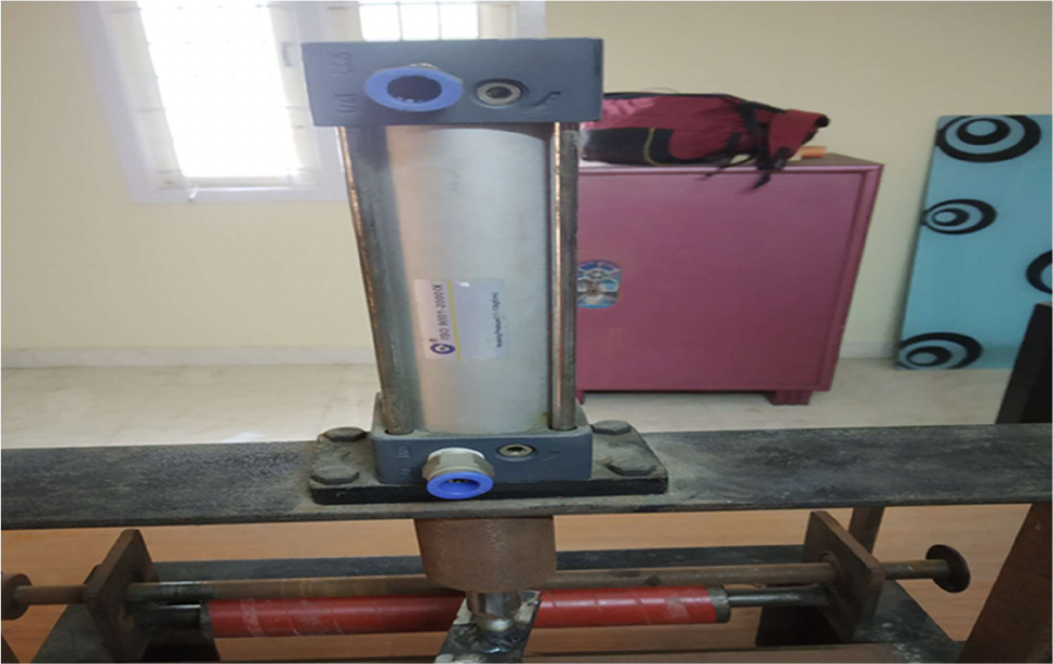
4.1.2 Double-acting Cylinder
This type of pneumatic cylinder have two ports to allow the compressed air into the
cylinder. Double acting pneumatic cylinder (shown in fig 4.1) uses the compressed air
to actuate the piston inside the pneumatic cylinder. The compressed air allowed into
the pneumatic cylinder through one port at the top of the cylinder. Once the
compressed air enters the cylinder due to the high pressure the piston moves from top
dead centre to the bottom dead centre and the force required for the punch and rivet
us obtained. When the piston head reaches the maximum stroke length, the
compressed air is passed into the cylinder through the second port at the bottom of the
piston. When the compressed air is passed to the bottom of the cylinder due to the high
pressure the piston moves from the bottom dead centre to the top dead centre. The
double acting pneumatic has two strokes namely compression stroke and expansion
stroke. During the compression the force required to punch or rivet the sheet metal is
obtained by means of reciprocating motion of the piston. During the expansion stroke
once the punch is finished the piston is settled to its original position with the help of
the compressed air. Both the single acting and the double acting cylinders are using
compressed air as the source. But they differ in the port design which allows the
compressed into the cylinder. Single acting cylinders are used in the factories where
force is needed in one direction. For example, ejecting the parts/items from the belt or
conveyor. Double acting cylinders are used in the industries for faster, stronger and
most effective applications. For example, when the work need to done is of high speed
and force industries prefer double acting cylinder. Since compressed air is used for
both compression stroke and the expansion stroke the work done is accurate and
reliable, most importantly the maintenance is low.
4.1.3 Advantages of Double-acting Cylinder
The control over the movement in doble acting cylinder is high because the
compressed air is used to move the piston in both ways.
Faster, stronger and uses less energy.
While using double acting cylinder in the manufacturing industries more bore
sizes and stroke lengths are available, we can use it according to the
requirements.
Since compressed air is used for actuating both the strokes maintenance is
low compared to single acting cylinder.

16
Table 4.1 End Cover Materials
Light duty
Medium duty
Heavy duty
Aluminium stock
(fabricated)
Aluminium stock
(fabricated)
High carbon steel castings
Brass stock
(fabricated)
Brass stock
(fabricated)
High speed steel castings
Aluminium castings Aluminium, brass, iron
castings
High speed steel castings
Table 4.2 Piston Materials
Light duty
Medium duty
Heavy duty
Aluminium castings
Aluminium casting
Brass(fabricated)
Aluminium forging,
Aluminium castings.
Aluminium forging
Bronze (fabricated)
Bronze (fabricated)
Brass castings
Iron and steel castings
Brass, bronze or iron and
steel castings

17
Table 4.3 Piston Rod Materials
Light duty
Medium duty
Heavy duty
Mild steel
Ground and polished,
ground, hardened, and
polished.
Generally preferred chrome
plated
Stainless steel
Ground and polished
Less scratch resistant than
chrome plated piston rod
Table 4.4 Specifications
Cylinder type
Bore diameter
Stroke length
Double-acting cylinder
65 mm
85 mm
18
Figure 4.1 Pneumatic Cylinder
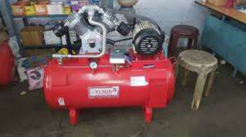
4.2 COMPRESSOR
Pneumatics is derived from the Greek word “pneuma” which means wind or breath.
Pneumatics is the branch of manufacturing engineering that uses compressed gas or
pressurised air in it. Pneumatic systems available in the manufacturing industries are
compressed air or pressurised inert gases. To produce these compressed or
pressurised gases some of the machines are used. An electrically powered
compressor (shown in fig 4.2) power cylinders, air motors, pneumatic actuators, and
other pneumatic devices are used. In factories pneumatic systems used for
manufacturing make use of the atmospheric air because they are readily available. The
atmospheric air is free of moisture content in it so some oil or any other lubricant is
used in the compressor to prevent corrosion and lubricate mechanical components.
Since we are using atmospheric air for the manufacturing it is free of poisonous
leakage. Some of the manufacturing companies are using asphyxiation including
nitrogen, makes up (78% of air) which is harmful to the workers. And the oxygen which
contains (28% of air) cannot used for compression because it is fire hazard, more
expensive and performance is low when compares to other gases.
19
Both pneumatics and hydraulics can be used for the compression of the air and
increase the pressure of the air by reducing the volume of the air. When compared to
hydraulics the pneumatics has the advantage of working even at the low pressure and
also the air which is needed for the actuation is readily available. But in hydraulics
system of compression separate oils should be bought and we must use it for the
lubrication purpose. The cost of the hydraulic fluids is high and also the construction of
the hydraulic system is little bit complicated when compared to pneumatics systems.
And the workers are finding difficulties in understanding the hydraulic system but
pneumatics is slight easier to understand and working.
Pneumatic system operates on the supply of compressed air to the machine and the
components. And mainly the compressed or pressurized air should be at a certain
quantity and also at particular pressure which is based on the capacity of the system.
Based on the capacity of the pneumatic system compressed air should be supplied
and for the compression of air compressor is needed. A compressor is the mechanical
device used to increase the pressure of the air by decreasing the volume of the air.
The capacity of the compressor also varies it is different based on the amount of air
that can be compressed at a unit time. Compressor capacity depends on the amount
and also the volume of the air that is to intake. The condition of the air to be intake is
also important because when the air is free from moisture is easy to compress. But
when the air warm and moist the compressed air is condensed and not up to the mark.
Compressor is of two types,
• Positive displacement compressor
• Turbo compressor
Positive displacement compressor are frequently used in the manufacturing
industries or factories and has proved the efficient type of compressor to supply the
compressed air. Positive displacement compressor is of two types,
• Reciprocating type compressor
• Rotatory type compressor
Reciprocating compressor is the basic type of compressor used all over the
manufacturing industries and companies. Reciprocating compressor is also called as
piston compressor. As the name indicates the compressor uses the piston which is
driven with the help of crankshaft to compress the air and deliver it. When the
crankshaft rotates the piston connected to the crankshaft starts reciprocating and due
to this the piston moves down since the atmospheric air is entered and the next stroke
the piston moves upwards and the air compressed by reducing the volume of the air

20
which entered the cylinder. And the compressed air supplied to the rest of the
pneumatic systems.
Turbo compressor works on the principle when the atmospheric air is sucked in then
the turbine rotates due to the flow of air. When the turbine rotates the air is compressed
by reducing the volume of the air. But the main disadvantage is that the turbo
compressor is not able to supply large amount if compressed air at particular pressure.
Turbo compressor is able to supply only small amount of compressed of low pressure
at a unit time.
The compressed air is supplied to the 5/2 directional control valve. This is also called
solenoid valve, which has 5 ports and 2 outlet ports. Among that 5 ports, 1 port are
used for the inlet of compressed air from the compressor, 2 ports is for outlet of the
compressed air to the pneumatic cylinder, and 2 ports is for the exhaust to release the
compressed air once the punching or riveting is done. The solenoid valve is parallel
connected with the microcontroller and also with the timer and the relay. The
microcontroller is mainly used to feed the sheet metal without the human work. By
doing this, safety of the worker is increased and the percentage of error to occur is also
reduced. Microcontroller in this system is electrically operated and according to our
requirements the appropriate programme is done in that way. The microcontroller is
parallel connected to the timer and the relay. The purpose of the timer in this pneumatic
punching and riveting system, is to count the number of seconds at which the sheet
metal should be feed and also the time(sec) at which the punch or rivet should be done.
And this input from the timer is passed to the microcontroller at every cycle. The
purpose of the relay in this pneumatic punching and riveting machine is to feed the
sheet metal according to the duration sent by the timer.
Table 4.5 Specifications of Compressor
Compressor type
Horse power
Max. pressure
Tank capacity
Reciprocating
compressor
7.0 HP
10 bar
70 Litres
21
Figure 4.2 Compressor
4.3 5/2 DIRECTIONAL FLOW CONTROL VALUE
Directional control valves are the most basic and fundamental parts of the pneumatic
and hydraulic systems. Directional control valves are mainly used for guiding the fluids
or air to the corresponding parts respectively. It may vary depending on the workers or
the customers need. Every directional control valve will have a spool inside it which
can be actuated mechanically or electrically based on the requirements and the need.
The spool inside the directional control valve will decide the direction of the fluid or air
to be supplied based on the requirements respectively. The spool inside the cylinder of
the directional control valve consists of lands and grooves. This lands and grooves will
decide the flow of the air or fluid. The lands will block the flow of the air or fluid where
it should not flow. The grooves will allow the fluid or air along the ports and the entire
spool where it should be supplied. In directional control valve there are two positions
normal and working positions. In normal position, the valve returns on removal of the
22
actuating force. In the working position the valve won’t return when the actuating force
is applied.
This directional control valve is selected rapid operation and also to reduce the
manual operation need to be done by the workers. Directional control valve is also used
for converting the pneumatic punching and riveting machine into automatic pneumatic
punching and riveting machine. Nowadays most of the manufacturing industries are
preferring automation in their every department of manufacturing. By using automation
in the industries, 90% of the work will be completed by the machines itself and rest
10% work will be completed by the workers. Due to this automation workers need is
reduced and the work is done perfectly. If the industry is without automation then the
management should search for lot of people for working and also the workers should
accept for the salary given by the industry. Most of the people attitude will be changing
day by day and they will take leave often. If the workers are not available then
automatically production will not be able to complete within the given date and time. If
the company chooses automation, they will invest their money only on the machines
which is good when compared to conventional type manufacturing. The single
automated machine will complete the entire work which need to be completed by the
thousands of workers. The industry will able to control the single machine which is easy
and profitable when compared to manual manufacturing. In conventional
manufacturing every thousands of workers need to be satisfied by the company in
terms of salary and safety precautions. So, in modern days most of the manufacturing
industries are using automation in their company.
Solenoid valve is the electrical device used for the converting the electrical energy
into the straight or linear force. Solenoid valve is also used for the conversion of the
mechanical work into automatic work. That is the work which is to be done by the
workers can be automatically done by the solenoid valve without any error and accurate
manner. Solenoid valve are of two types namely push type and pull type. In push type
solenoid valve, the plunger is pushed when the solenoid valve is actuated electrically.
And in the pull type solenoid valve, the plunger is pulled when the solenoid valve is
actuated electrically. The workers should be well known about the parts and the
working of the solenoid valve because if the solenoid valve repairs workers should be
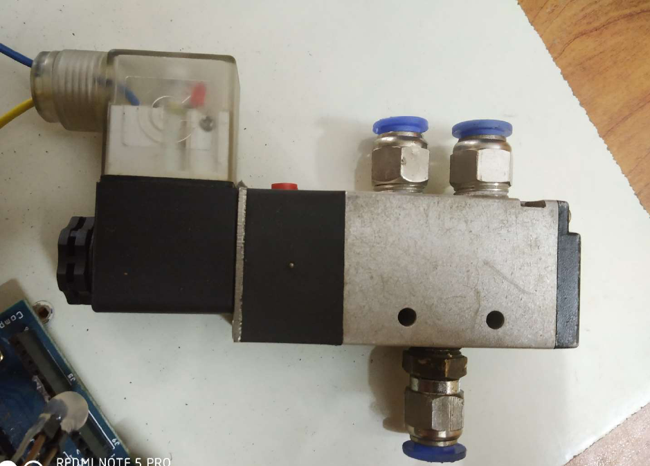
able to rectify it and continue their process. The compressed air is supplied to the 5/2
directional control valve (shown in fig 4.3). This is also called solenoid valve, which has
5 ports and 2 outlet ports. Among that 5 ports, 1 port are used for the inlet of
compressed air from the compressor, 2 ports are for outlet of the compressed air to the
pneumatic cylinder, and 2 ports is for the exhaust to release the compressed air once
the punching or riveting is done.
23
4.3.1 Parts of 5/2 Solenoid Valve
Solenoid valve is the easiest valve to understand and work with it. There are some
parts in the solenoid valve we need to see. Because the workers should be aware of
the parts and the function of the solenoid valve. If it gets stopped or repaired then the
workers should able to rectify the problem. These are the three main parts of solenoid
valve,
Coil
Frame
Solenoid plunger
Coil
The solenoid valve consists of coil inside it which is the core of the valve. The coil which
is present inside the solenoid valve is made up of copper wires. The coil will consists
of thousands of wires for the specific purpose. And these copper wires are separated
from one another with the help of the insulating layer. The whole solenoid valve is
covered with the help of vanish and due to this the solenoid valve is protected from the
external disturbance. The disturbance may be by solvents, moisture, cutting oils, or
often fluids. The coils present inside the cylinder may be vary according to the operating
voltage. The operating voltage available till date are 115 volts AC, 230 volts AC, 460
volts AC, 575 volts AC, 6 volts DC, 12 volts DC, 24 volts DC, 115 volts DC. The
frequency of the actuation of the solenoid valve is 50 Hz to 60 Hz.
Frame
The solenoid valve is designed in such a way that the valve is applicable for all purpose.
The frame which is used for the construction if the solenoid valve is also for the several
purposes. The frame of the solenoid valve is made of laminated sheets, the laminated
sheets has the advantage of auto magnetize itself when the solenoid valve is
electrically connected. The main purpose of using the laminated sheets is that the
plunger is pushed or pulled using the magnetising effect in the frame. The frame
consists of the provisions for the attachment to the external parts. They can be bolted
or welded along the frame to actuate the solenoid valve. The wear strips are connected
to the frame and they are made of materials such as metal or impregnated less fibre
clothes.
Solenoid plunger
The solenoid plunger is the most important part of the solenoid valve. Through which
the workers will feed the input to the solenoid valve. Solenoid plunger is the movable

24
part which can be pushed or pulled according to the requirement. The solenoid plunger
is made of thousands of laminated steel which is connected by riveting it along one
another through applying high pressure. It is connected by riveting the each and every
layer so that there will be no movement between the layers. The solenoid plunger can
be operated in two ways, either by applying input in manual method or by connecting
it to the electrical devices. At the top of the solenoid plunger a pin hole is present
through which the solenoid plunger is connected to the other devices for actuation.
When the solenoid plunger is operated electrically the plunger will move initially by
means of magnetic force and then the plunger will return to the original position by
means of spring action.
The valves which are operated by the solenoid valve are generally provided with
the cover. This is mainly to prevent the ports and the solenoid valve from the dust and
other foreign matters and to protect the actuator. Most of the manufacturing industries
are using explosion proofs solenoid valve for the manufacturing purpose.
Table 4.6 Specifications of Solenoid Valve
Type
Operating pressure range
Ports
5/2 directional control
valve
2 to 10 bar
1,2,4-G 1/43,5-G 1/8
25
Figure 4.3 5/2 Dirctional Control Valve
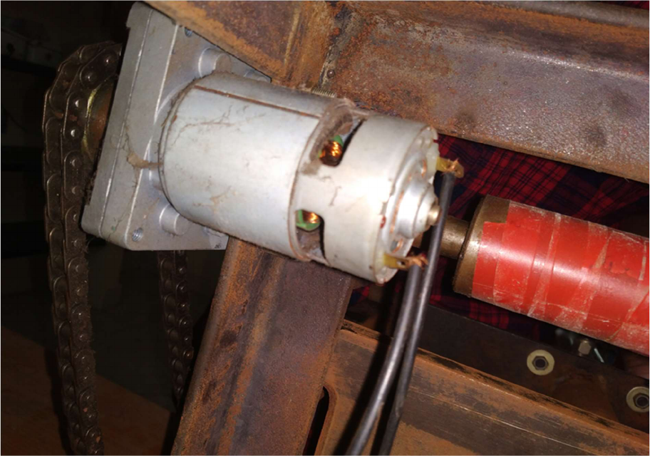
4.4 DC Motor
The DC motor (shown in fig 4.4) is one of the types of rotary electrical motors. DC
motor is the electrical device that converts the electrical energy into mechanical energy.
The main thing in DC motor is that the input electrical energy should be in direct current.
All the DC motor will have internal mechanism in it which is used to convert the
electrical energy into the mechanical energy. It may be electrochemical or electronic to
constantly change the direction of the current in the motor. It is the first and the foremost
form of motor used all over the world. This DC motor can be powered using the direct
current electrical systems. The DC motor speed can be changed according to the need
by either changing the supply voltage or by changing the strength of the current in the
windings. We can see wide range of DC motors are used for example small DC motors
are used in toys, tools, and appliances. This universal motor can be operated using
direct current anywhere needed. Brushed DC motors are widely used because it has
an advantage of portable power tools and appliances. Larger DC motors are rarely
used in propulsion in vehicles, elevator and hoists, and in drives for steel rolling mills.
26
The brushed DC motor will generate torque directly from DC power supplied to the
motor with the help of internal commutation, stationary magnets that is permanent or
electromagnet and rotating magnets. The brushed DC motor has the advantage of low
initial cost, very high reliability and easy control of motor speed. But at the same time
brushed DC motor has equal number of disadvantages like high maintenance costs
and low life span for high intensity of current usage. The maintenance involves regular
replacement of the carbon brushes which carries the current and springs used for the
conduction of current. And also the commutator should be cleaned regularly or else the
dust will affect the efficiency of the motor. These components are necessary for
conduction of the direct current from the outside of the motor to the spinning windings
inside the motor.
In the brushed DC motor the brushes are commonly made up of graphite or carbon,
and in some cases the brushes are dispersed with the copper to increase the current
conduction due to this the efficiency of the DC motor is also increased. The brushes
which make contact with the commutator is replaced with some soft brushes, so the
brushes fit to the diameter of the commutator and the wear and tear is reduced. The
brush holder has a spring to maintain pressure on the brushes to prevent the efficiency
decrease while the current is not supplied at constant manner. The brushes which
carries one ampere or more than one ampere, the brushes are moulded with a flying
led to the motor terminals. Very small brushes may experience the contact with the
metal brushes holder for carrying current into the brush. The DC motor which are used
in toys and other small tools are made up of folded strip of metal that connects the
commutator.
In brushless DC motor, one or more permanent magnets in the rotor and
electromagnets on the motor and for the stator. In the brushless DC motor, a motor
controller is used for the conversion of DC current into ac current. The design of the
brushless DC motor is simple when compared to brushed DC motor. The brushed DC
motor will have some conduction of the direct current from the outside of the motor to
the spinning motor inside the DC motor. The motor controller can sense the rotor
position through hall effect sensors and similarly control the timing, phase, etc of the
current rotor coils to optimise torque, conserve, power, regulate speed, and even
applying some braking when needed. The advantages if the brushless DC motor long
life span, little or no maintenance and high efficiency. The disadvantages of brushless
DC motor is that the initial installing cost is high and mor complicated motor speed
controllers. The brushless DC motor is also known as synchronous motors they have
no external power supply to synchronize. In this pneumatic punching and riveting
machine, the sheet metal is feed automatically. To feed the sheet metal the
microcontroller is connected with the DC motor. The DC motor is a electrical device
that convert the electrical energy into the mechanical energy. Once the input from the

27
timer and the relay is obtained by the microcontroller, the DC motor is actuated
accordingly by the microcontroller. The rotational speed of the DC motor will be high
so that we should some gears to reduce the speed according to our requirements. The
driver gear is attached with the set of rollers at the same time the driven is also attached
with the set of rollers. These roller plays a major role in the auto-feed of the sheet metal
for punching and the riveting machine to punch or rivet. And this input from the timer is
passed to the microcontroller at every cycle. The purpose of the relay in this pneumatic
punching and riveting machine is to feed the sheet metal according to the duration sent
by the timer
4.4.1 Advantages of DC Motor
Drive circuit is not needed when the DC motor is running at a constant speed.
The design of the brushed DC motor is done in such a way that it has high
efficiency.
Brushed DC motor can be operated at high speed and high current.
When the DC motor is starting the current can be high and also the torque
produced due to this can also be high.
By using brushed type of DC motor the speed and torque can be controlled and
responsive by controlling the voltage.
Table 4.7 Specifications of DC Motor
Type
Supply voltage
range
RPM
Gear assembly
Brush type DC
motor
4 to 12 Volts
30 RPM at 12 V
Heavy duty metal
gears
28
Figure 4.4 DC Motor
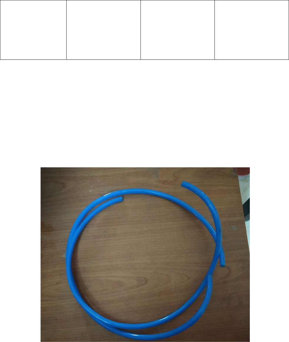
4.5 PNEUMATIC HOSE PIPE
The basic function of pneumatic hose pipes(shown in fig 4.5) is to transfer the
compressed from the compressor or from one to another parts where the air needed
without losing the pressure of the air. In market there are several number of pneumatic
hose pipes are available for sales. The engineers in the manufacturing industries will
select the pneumatic hose pipes according to the requirements. Engineers will mainly
consider the construction of the pneumatic hose pipes. The tubing of the hose pipes
may be extruded with single material, or the outer layer is done with one material and
the inner layer is finished with the help of another material. Most of the pneumatic hose
pipes are made up of textile fibres, for higher strength. Pneumatic hose pipes is of two
layers, the inner tube layer is made up of one or more layers of reinforcing braided or
spiral wound fibre. The outer layer of the pneumatic hose pipe is made up of protected
cover to prevent the external damage.
29
The next main criteria of selecting the pneumatic hose pipes are the air supply and
the flow requirements. Once the design and the construction are done by the engineers
in the manufacturing industries. Then the engineers will consider the capacity how
much the hose pipe will supply or pass the air through it. Generally tubing of the hose
pipe is done by considering the outer diameter, inner diameter and wall thickness.
When the hose pipes are with less inner diameter will leads to loss in the pressure of
the compressed air, low efficiency, and low life span. At the same time when hose
pipes are constructed with high inner diameter then the weight of the hose pipe, size
and also the cost of the hose pipe will increase which results in loss to the industry.
Manufacturers basically fix the tubing measures using the burst pressure of 75 F, then
they divide it by safety factor to calculate the maximum working pressure. While buying
a pneumatic hose pipes from market the maximum working pressure will be mentioned
in that and the manufacturers should not operate the hose pipes beyond that pressure
for their safety measures. Since we are using atmospheric air for the manufacturing it
is free of poisonous leakage. Some of the manufacturing companies are using
asphyxiation including nitrogen, makes up (78% of air) which is harmful to the workers.
And the oxygen which contains (28% of air) cannot used for compression because it is
fire hazard, more expensive and performance is low when compares to other gases.
Normally the tubing of the pneumatic hose pipes is done with the help of
thermoplastic tubing. But the engineers from the manufacturing industries are choosing
it in various countless materials for the production based on the requirements. But
typical tubing material used for the pneumatic hose pipe is polyurethane tubing. The
polyurethane tubing is very strong, flexible according to the customer need, abrasion
resistant it also with stand the contact with fuels and oils. Polyurethane tubing is most
commonly sued in robotics, pneumatic actuation, logic systems and vacuum
equipment. And also, the polyurethane tubing is widely used for the semiconductor
manufacturing, medical and laboratory applications. Nylon tubing is also used in the
tubing of pneumatic hose pipes but it is not much effective as polyurethane tubing.
Nylon tubing are used in low pressure it is tough, light, and dimensionally stable. Nylon
tubing are used mainly for high pressure pneumatics, flexibility for routing in tight
spaces, low water absorption can be used in the water applications.
Polyethylene tubing is used only for the low- pressure pneumatics. But polyethylene
tubing has an advantage of chemical resistant and solvents resistant. Polyethylene
tubing have good flexibility and available at low cost. High graded polyethylene tubes
are having the major advantage of resistance to the cuts and external damage which
leads to the pressure loss. The polyethylene tubes are having high burst pressure when
compared to the polyurethane tubing.

30
Polyvinyl chloride tubing is very light and more flexible when compared to the
polyethylene and nylon tubing. It also offers good chemical resistance and can be
frequently stabilized. Polyvinyl tubing is suitable for the low-pressure medical
applications and can be used for the FDA specifications for the direct contact with the
food and drugs. Polyvinyl chloride tubing is clear to the human eyes and suitable for
the visible indication of the flow is necessary. Polypropylene tubing is suitable for the
direct food contact applications and also the polypropylene tubing is good chemical
resistant and withstand the ultraviolet radiation in outdoor applications.
There are basically two common physical characteristics we need to consider while
choosing pneumatic hose pipes. They are flexibility and kink resistance of the tubing
done for the hose pipes. This the best characteristics among all when selecting
pneumatic hose pipes rather than looking at the manufacturer need. The another
selecting criteria is colour, tubing comes in wide range of colours as well as clear
depending upon the material used for the tubing of pneumatic hose pipes. Finally, the
tubing of the hose pipes should meet the rules and regulations of the ISO and FDM.
The compressed air is supplied to the 5/2 directional control valve. This is also called
solenoid valve, which has 5 ports and 2 outlet ports. Among that 5 ports, 1 port are
used for the inlet of compressed air from the compressor, 2 ports are for outlet of the
compressed air to the pneumatic cylinder, and 2 ports is for the exhaust to release the
compressed air once the punching or riveting is done. Both pneumatics and hydraulics
can be used for the compression of the air and increase the pressure of the air by
reducing the volume of the air. When compared to hydraulics the pneumatics has the
advantage of working even at the low pressure and also the air which is needed for the
actuation is readily available. But in hydraulics system of compression separate oils
should be bought and we must use it for the lubrication purpose. The cost of the
hydraulic fluids is high and also the construction of the hydraulic system is little bit
complicated when compared to pneumatics systems. And the workers are finding
difficulties in understanding the hydraulic system but pneumatics is slight easier to
understand and working.
Table 4.8 Specifications of Hose Pipes
Pipe
made by the
material
Diameter in (mm)
Wall thickness in
(mm)
Length used in
(mm)
31
Figure 4.5 Hose Pipes
Polyurethane hose
pipes
15 mm
4.1 mm
100 mm
(2 sets are used)
32
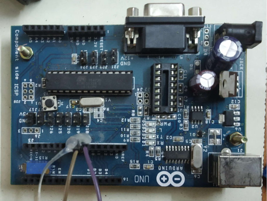
4.6 MICRO CONTROLLER
A microcontroller (shown in fig 4.6) is integrated compact circuit designed to govern a
specific operation in an automated system. The important components of a micro
controller include a processor, memory, input connections, output connections in a
single chip sometimes these micro controllers are referred as microcontroller unit and
it is also called as embedded controller these micro controllers are found in vehicles,
mobiles, radios, vending machine, and these micro controllers are also found in
home appliances and in another daily device that we use.
Figure 4.6 Microcontroller
33
These micro controllers are miniature personal computers which are essential to
carry out certain processes which involves in automation or controlling of large
components small features without a complex algorithmic process or a complex
operating system. Most of the automated devices will contain a microcontroller these
micro controllers are low in cost and also low in weight when compared to the old
programmable logic controller which are twice its size and the algorithm used in this is
so complex when compared to the modern micro controller that are being used now a
days. In which mixed signal micro controller are being used common now a days due
to its capacity to work with different out signals like the microcontroller get signal from
different sensors in different signal format like light, sound, movement all these signals
are of different types so the micro controller converts all these different signals into one
signal to perform the desired operations the input signal may be analog signal or digital
signal. Micro controllers are cheap data collecting tool which uses the information that
it gathered from the sensors and use these data to perform action like actuation and
other sensing operations. Some micro controllers use 4-bit and operation frequency of
these microcontrollers are 4 kHz for low power consumption most of the micro
controller acts as the digital signal processor. In addition to this there are 8-bit micro
controller which uses 16 kHz of power consumption the difference between the 4-bit
and the 8-bit micro controller is the amount of data which is being controlled or sensed
or collected or displayed the higher the bit the amount of data and signal which are
being controlled need more power to do the process. When lower control is required 4-
bit micro controller is used so that the power consumption will be reduced in turn
reducing the overall cost and overall weight of the final product.
4.6.1 Elements of Microcontroller
1. THE CENTRAL PROCESSING UNIT
The central processing unit (CPU) which is responsible for Arithmetic
operation’s, control signals, manages data flow in relation with the code given
by the programmer. The programmer doesn’t have any problem with the
functionality of the device which is the responsibilities of the integrated
development environments and complex language like C which is use to
program the controller
2. MEMORY
A read only memory (ROM) is used in a microcontroller this memory is also
called nonvolatile memory which refers to the memory in which data can retain
itself after a shutdown. This memory is the place where the program is being
stored and the program is machine language that instructs the CPU exactly what
process has to be done. The word “Flash” is used in the microcontroller which
indirectly denotes nonvolatile data storage. Temporary memory also known as
34
volatile data storage or also called random access memory (RAM). The data
which is being stored in this is lost when the power to the controller is turned off.
process which are being done by volatile data is faster when compared to
nonvolatile storage.
3. PERIPHERALS
The word peripherals mean the other modules that are being used or that
helps a microcontroller to communicate with the external system to perform the
required operations the following are the categories of the peripherals
DATA CONVERTERS: Data converters convert analog signal to digital
signal and vice versa like digital signal to analog signal references and
also reference voltage generator.
CLOCK GERERATION: This component deals with the internal
oscillator, phase locked loop and drive circuit.
TIMING: The general purpose of timer is to manage the time difference
by the use of real time clock timer and event counter
ANALOG SIGNAL PROCESSING: Analog comparator which helps in
the process of conversion or generation of analog signal
INPUIT: The input of the microcontroller includes the connections of
ethernet or any external USB drives to perform the operations of giving
input data to the microcontroller
OUTPUT: The output connection is made by the bread board to various
components to perform various tasks like connecting the sensors so that
the input data can be transferred to various sensors for output generation
SERIAL COMMUNICATION: USB, I2C
4. SUPPORT CIRCUIT
The micro controller has a variety of functional block which cannot be
classified or comes under the periphery. The support circuit does not have any
primary job like control, monitor or communication with external components.
The use of support circuit is that they support the internal operations like
implementation and development process. These processes are carried out by
different components like
Debug circuitry: This allows the programmer to monitor the
microcontroller as the instructions are being executed. This is an
important process to take down bugs for improving the performance
Interrupts: This is a most important component of a microcontroller
functionality this component is an external hardware component this
cause the component for specific instructions.
35
Clock generation module: This module can be determined as a
peripheral if it was to send signal but instead this module is used to
provide internal oscillation signals to the CPU. These modules have low
precision but this is capable to tolerate the low precision signals this
module is used to save space in the microcontroller board and for a
simple design.
Power supply circuit: Integrated voltage regulators allow the
generation of required voltage and power management properties can be
sued to reduce the devices power consumption during in active state and
can place the processor in a stable voltage supply for volatile data
storage system.
4.6.2 Working of Microcontroller
The microcontroller is embedded inside a system as a singular functional device. The
micro controller does this by compiling the data it gets from the input sensors or the
output sensors or the peripherals using its central processing unit. The information
which are required temporarily are stored in the volatile data store (RAM), the
processer access it use the program I in it to carry out the process and apply the data
in it to get the necessary data and it uses the input and output peripherals to
communicate with the other components of the sensors to get the required data or to
perform the required actions. These microcontrollers are used in wide variety of
systems and devices. In some case some devices use multiple microcontrollers to
perform multiple tasks in which the microcontroller works together to perform their
respective tasks. Like a device may contain multiple microcontrollers like one to
perform one specific operation and a another to perform another operation the two
microcontroller has to work together so that their individual work can be done easily.
The micro controller has a specific complex instruction set computing and reduced
instruction set computing. The complex instruction set computing has around 80
instructions that can de done at one in a device to make it more useable. While the
reduced instruction set computing has a instruction limit of 30 so the data storage used
in this is low when compared to the CISC controller but the CISC controller is more
efficient and compactable in automating process.
4.6.3 Features of Microcontroller
The microcontroller is subjected to change based on the application it is being used.
The processor varies from 4-bit, 8-bit, 16-bit to more high-power processors like 32-bit
36
and 64-bit processors. Microcontroller can even vary based on the type of data they
handle like volatile data storage and nonvolatile data storage which means Random
Access Memory (RAM) or permanent memory and Read Only Memory (ROM) or
permanent memory and Electrically erasable programmable read only memory
(EEPROM). Generally micro controllers are used as a device which is readily available
without any additional components because while designing readily memory is already
available to use instead of expanding and in addition to this the microcontroller board
has pins for input and output operations so they can be used directly with the sensors
without any interference of other components.
The architecture of microcontroller is based om the Harvard architecture which offers
exchange of data from one version or model to another version or model of
microcontrollers the data bus and instructions are separate in this architecture so the
transfer of data is easy when compared to other architecture. The microcontroller
processor the micro controller has a specific complex instruction set computing
(CSISC) and reduced instruction set computing (RISC). The complex instruction set
computing has around 80 instructions that can be done at one in a device to make it
more useable. The CISC’s is easy to implement and work on due to the vast memory
it provides and has performance at its best due to the higher number of clock cycles
need to execute a program. While RICS which relay more on the software for
performance when compared to CISC type. While the CISC type microcontroller relay
more on the hardware part of the microcontroller, and it has a compact design due to
the complex hardware parts. Were the RISC having a simple design due to simple
hardware parts and complex software. During the initial stages of the micro controller,
they mainly depend upon assembly language for their operations, but now days other
languages like python, C, C++ can be used to program a microcontroller. The
microcontroller units use pins to implement the input and output operations from the
peripherals to the sensors. Even the sensors are connected to the microcontroller
through the pins. The function also includes the conversion of signals and liquid crystal
display can be connected to the controller for monitoring purpose and real time clock
can also be attached to the controller with the help of pins. Universal synchronous or
asynchronous receiver is also provided with most of the controller for wireless
transmission and universal serial bus (USB) connectivity is also used in microcontroller.
The sensors collect data from different source and convert the signal using these
features to get the end result or to perform an automation process.
4.6.4. Types of Microcontroller
1. Intel MCS-51
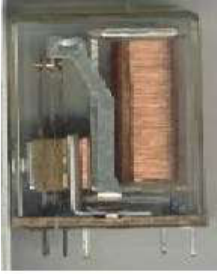
37
2. AVR microcontroller
3. Programmable interface controller (PIC)
4. Advanced RISC Machine (ARM)
4.7 RELAY
Figure 4.7 Relay
Relay(shown in fig 4.7) can be defined as a switch. Which is generally used to open
and close the circuit manually relay is also a switch that is used to connect two circuit
or close two circuits but instead of manual operation relay uses electrical signal to
perform the operation of connections and disconnections. And relay is used to control
a circuit of higher voltage than the input voltage it can also be called as an electrical
amplifier. The relay is also used to refresh the signal from one circuit to another circuit.
Relay uses an electromagnet to connect to a circuit or disconnect that circuit. Besides
this there are other types like solid state relay which uses the properties of
semiconductor for the process of connections to the circuit or disconnection of the
circuit by zero moving parts. Relays multiple coils to prevent from overloading to protect
the electrical circuit. In modern systems these functions are performed by digital relays
called protective relays.
Some relays only require only single pulse of control power to connect the switch.
When a negative pulse if given to the relay it will discount the circuit repeated pulses
of same kind will have no effect
38
4.7.1 Components of Relays
1. RELAY CONTACTS
A relay has two fixed contacts which is denoted by “NC” normally closed and
“NO” normally open. These two contacts have a common movable contact
called “COM” or common under normal conditions in which a relay can be either
open or closed. These contacts are conductors made up of electricity conducting
material’s and they have a contact strap on it these contact straps also has high
conductivity and this strap is resistance to electric spark. This property provides
protection when sudden high voltage passes through it. These metals are used
to close the circuit allowing electricity to flow through it. These contacts should
be monitored that if the resistance and conductivity are constant.
2. ELECTOMAGNET
When current passes through the conductor magnetic field is produced
similarly when is being passed through a coil wounded in a soft iron a magnetic
field is created perpendicular to the direction of the current. This magnetic field
is converted into an electromagnet when it passe through the iron core,
magnetic properties will be present in the electro magnet until the current is
disconnected. So, this electro magnet has an important role in the relays working
principle even in most cases the magnetic field is retained by the magnet even
after the current is disconnected. This is done by the magnetic lag which is
created by hysteresis. To nullify the magnetic property in the iron core a small
magnetic force can be applied.
3. MOVABLE ARMATURE
The armature is a moving conductor in the relay which is used to connect or
disconnect the contact based on the amount of magnetic flux in the iron core.
When electricity passes through the armature it will be pulled against the spring
due to tension to connect or disconnect the contact based on the relay type
(normally closed or normally open). Due to some fault in the current it may cause
unintentional triggers in maintain the spring tension. An armature can be
unbalanced by the addition of regular plastic covers. The disadvantages of these
type of armature are that these types are easily affected by external factors.
Relays having balanced armature can counter external force or any sudden
increase in voltage. Two types of armature can be used for both direct current
and alternative current but alternative current can cause increasing pulsating
magnetic field this will cause the armature to connect and disconnect the contact
for each half-cycle. Shader ring can be placed in the iron core in the armature
to prevent the pulsating magnetic field.
39
4. YOKE
The yoke is attached to the soft iron core which is an electrochemical metal
piece. Which is used for attracting and holding the armature. The yok is attached
to the top of the of the iron core element in most of the relay the armature is
connected to the yoke with the help of a conducting wire which is used as a
connectivity or the continuity of electricity between the armature and the contact.
The yoke also provides low reluctance path to the magnetic flux that passes
through the armature and the contacts. The primary circuit has the movable
armature and the sprint the yoke is the small material which connects them to
make the primary circuit. Due to magnetic field the is responsible for the pull of
armature coil to the contact for the process of connection and disconnection.
5. SPRING
Springs are attached to the armature coil for its easier movement. When
magnetic field is generated the for the process of connection and disconnection
the contacts during this process the spring allows the armature to move freely.
These springs are usually made up of sheet metal. In some high-performance
relay, the spring will be made up of nickel silver. A relay will be useless when
there is reduction in spring tension. Thus the spring should be in a good
condition to use the relay.
4.7.2 Working of Relays
A simple electromagnetic relay has a coil of wire wrapped around a soft iron core also
called a solenoid a low reluctance path for magnetic flux is provided by an iron yoke
and a movable iron armature and two set of contacts. The armature is connected to
the yoke and mechanically to one or more sets of moving contacts. A spring is used to
hold the armature in place so when the coil is de-energized a gap is formed in the
magnetic circuit so in this condition one of the contacts is will be closed and the other
set of contact will be open. Depending on the functions of the relay one or many
contacts will be used a wire will be connected between the yoke and the armature this
for the continuity of the circuit the yoke is attached to the board by using a soldered
mechanism. Magnetic field is generated when the electric current is passing through it
which activates the armature. The consequent moment of the armature makes the
movable contacts either to break or make a connection with a fixed contact. If the
connections were closed during the de-energization of the relay the contact breaks the
connection by opening the movement and if the contacts were open during the de-
energization of the relay the contact makes the connections by closing the movement.
The armature will return the force half as strong as that of the magnetic force when
40
switched off. Spring is responsible for providing this force but in industries the starter
force is provided by gravity. Relays can even operate on low voltage. Noise is reduced
in low voltage and during high voltage the electrical arcing is reduced.
There will be surge currents in the relay output if the relay is driving a large or high
load. So, a snubber is used in between the contacts to reduce the surge between each
contact when high load is being passed through the relay. While using alternative
currents the flux produced should be split into two out of space components which
increase the pull during the usage of alternative current. Usually this is done by using
a copper ring around the core which creates a delayed out of phase component which
controls the voltage during the initial contact of the contacts with movement. Contact
materials for relay vary by applications low resistance martials which are oxidized by
the air should be used for low resistance and the material should have high heat
resistance since this material will be active through the process when electricity passes
through it the conduction should be also high.
4.7.3 Types Of Relays
1. LATCHING RELAY
Latching relay are also called keep relay which has two relaxed states. The
relay will remain in disconnected state when the current is switched off a cam
mechanism and a ratchet operating solenoid are responsible for this process or
by having a positive and a negative coil which are opposing each other with a
permanent magnet at center to hold the armature and the position of contacts
in the coil are relaxed or with a remnant core. The first pulse of the coil turns it
on and the second pulse turns it off.
If the pulse to one of the coils connects the relay and turn it on and a pulse to
the opposite coil will disconnect the circuit and turn off the relay. The relay only
consumes current for an instant while turning it on. Latching type relay has a
remanent core that is used to mark the position of the contact. This is used to
retain the contact by magnetism which will be present in the core during
energizing process. A permanent magnet will be used to produce a variation in
the force required to close the contact. The is responsible for providing the
necessary force required to connect and disconnect the contact from the core
which is done by opposing the magnetic field or adding up of the field of the
permanent magnet. The latching relay can only be controlled by a switch which
is connected to the circuit. The latching relay is less expensive when compared
to other types of relay but its cost may increase based on the use of an external
circuits.
41
In another type latching relay has a rachet mechanism in which the coil will be
momentarily energized when the contacts are being closed. This is done by the
first impulse while the second impulse is responsible of the release of the second
contact which will produce the sane energy which is similar to the first impulse.
2. REED RELAY
Reed relay has contacts which are placed inside vacuum or a glass tube filled
with inert gas which is use to protect the contact from correction. When current
passes through the circuit magnetic field is formed around the contact. Reed
relays are capable for the fast switching between open and close circuit and
requires low voltage for operation when compared to other types of relays. Reed
relay can switch to different connection faster than larger relays and the power
required is very low when compared to other relay of this size. On some rare
occasions these types or reed relay can be magnetized over time which make
then attractive in nature like to stick on to the opposite poles even when the
current to it is turned off. These types of relays have more operating lives when
compare to other relays. These types of relay has relative low voltage when the
switching of the contacts happen.
3. MERCURY WETTED RELAY
These relays used as high current connecting switches or contactors, where
erosion of contact is a problem in most of the conventional relays contact.
Mercury relays are not mostly sued in modern applications these mercury
wetted relays are being replaced by solid state relays. As the name denotes this
relay has a mercury tube in a vertical position. The bottom of the tube is
isolated and in a side up arm of the glass. The working of the relay is based on
a slug which is placed in side the mercury tube will sink due to gravity due to
this displacement of mercury takes place this displacement is responsible of the
rise of mercury in the tube so that the circuit will be complete now due to the
contact of mercury and the other parts of the relay. The coil is placed at the top
of the tube this coil is responsible for the attraction of the slug. So, when the coil
is subjected to electricity the coil will attract the slug and thus in turn the mercury
will be displaced by the slug. The glass tube of mercury should be mounted
vertically the sensitivity of the relay can be adjusted by the angle relative to a
vertical position. The high-speed switching action of the mercury rely is one the
best advantage that it can get.
42
4. POLARIZED RELAY
A Polarized Relay contains a permanent magnet the inducts magnetic flux
to the coil the permanent magnet is also responsible for the transfer of flux to
the two contacts that are place at the centre of the coil. The contacts are
associated with the other components to transfer the armature current through
the electromagnetic coil using the correct polarity of positive or negative. The
current pulse will energize the coil of proper current of one flux while the other
flux is reversed in the armature the polarized relays are usually small in size and
have faster operation speed and have higher resistance to shock and vibration.
5. FORCE GUIDED CONTACTS RELAY
In this type of relay, the contacts are connected together using mechanical
linkages. When electricity is being passed to the core all the contacts will move
together as one since all the contacts are linked mechanically. If one of the
contacts is immobilized not even a single contact will move due to the
mechanical linkage. This process is used to maintain the safety of the relay
these relays are also known as positive guided contacts or captive contacts or
safety relays. These safety relays follow a certain design rule since this relay
depends upon mechanical linkage most of the time the contacts should be
checked since there is no guarantee that all the contacts re in the same state as
the other contacts.
4.8 TIMER
The timer is a combination of an electromagnetically output relay and a control unit. In
this the contact will open after a predetermined time or after some time interval. The
timer is initiates or triggered by different methods like by the application of input voltage
supply will connect or disconnects the trigger the trigger signal can also be a control
switch or a power voltage trigger.
43
4.8.1 Types Of Timer Function
1. DELAY ON
During the start of the timer there is a delay on the pull-in which acts as the
delay of signals.
2. ONE-SHOT (FALLING EDGE)
When an input voltage is applied the timer will be ready to accept the trigger.
So, the trigger will be triggered which will leave the output de-energized.
When the trigger is remover the output will be energized so at the end of the
time delay the output will again be de-energized.
3. DELAY ON AND DELAY OFF
The timer needs a voltage supply so that it can be activated and
deactivated with an external contact or with a DC voltage. When activated
there will be a pull in and which will de-energize the timer on the drop out of
the delay
4. DELAY OFF
When no voltage is given to the timer there will be a delay on dropout
without any power supply
5. TWO-SHORTS (RISING EDGE AND FALLING EDGE)
When input voltage is given to the timer the trigger will be triggered upon
the signal based on the time interval set the other process will be executed.
6. FLASHING
During the application of input current, the time delay will begin the output
will be energized at the end of the tome delay it will remain the same for
some time. The output will be de-energized at this time and it will remain like
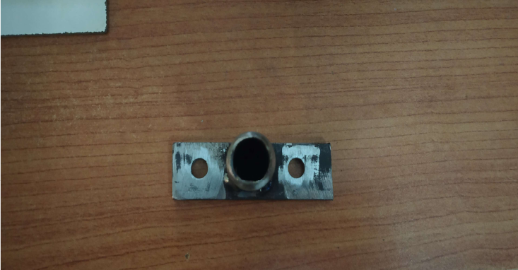
44
this until the end of the time delay. After the end of the time delay the output
will be energized and this will be repeated until the next sequence.
4.9 PUNCHING TOOL
The punch tool(as shown in the fig 4.9) used here is made up of high-speed steel and
has a double shear which is used to Pearce the metal sheet with minimal effort and the
design of the punch tool is flat with an opening in the middle with outside shear model.
So, the stress distribution in the punch tool starts from the middle to the radial side of
the tool. This double shear punching tool is also used or reduced force due to
symmetrical distribution of force while the single shear tool in which the force
distribution is higher in the higher degree and may cause bending due to non-even
symmetry.
Figure 4.9 Punching Tool
4.10 RIVETING TOOL
The Rivet tool ( as shown in the fig 4.10) used here is made up of mild steel the bottom
of the tool is like old punching tool of full metal in a cylindrical shape which is used to
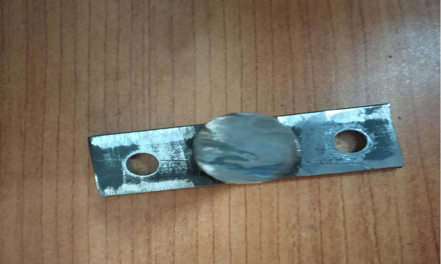
45
ram the nut rivet in the sheet metal this type of rivet is used for blocking the punch hole
and also used to join two material the main advantage of this riveting process is that
the hardness of the nut rivet after the process of riveting is high due to the ramming
process done here.
Figure 4.10 Riveting Tool
4.11 WORKING PRINCIPLE
The compressed air from the compressor is used to punch or rivet the sheet metal with
the help of cylinder, piston and piston rod. The pneumatic cylinder converts the
pressure of the compressed air into the mechanical force needed to punch or rivet the
sheet metal. The pressure of the compressed air is converted into the mechanical force
by reciprocating motion of the piston and the piston rod. When the compressed air is
46
supplied to the top of the cylinder the piston moves from top dead centre to the bottom
dead centre, and the punch or rivet is done. When the compressed air supplied to the
bottom end of the cylinder the piston moves from bottom dead centre to the top dead
centre.
4.11.1 Working
The atmospheric air is collected by the compressor and with the help of the
compressor parts the atmospheric air filtered and cleaned in order get good efficiency.
The atmospheric air is compressed, the pressure of the atmospheric air is increased
by decreasing the volume of the atmospheric air. The compressed air can be regulated
at particular pressure rate with help of pressure gauge according to the requirements.
The compressed air at the pressure of 8 to 10 bar is supplied to the solenoid valve with
the help of pneumatic hose pipes. The pneumatic hose pipes are used since they do
not lose the pressure of the compressed air need to be supplied. The solenoid valve is
used to supply the compressed air to the pneumatic cylinder. The solenoid valve can
be actuated in both either automatic or manual. The solenoid valve is connected to the
microcontroller for the auto feed mechanism. The microcontroller is connected with the
timer and the relay, because the timer is used to count the number of seconds the feed
needs to be done and the relay is used to actuate the DC motor for the auto feed for
the required timing. The DC motor is the electrical used to convert the supplied
electrical energy into the rotational energy. And the rotational energy obtained by the
DC motor is supplied to the rollers by adjusting the speed of the motor using
mechanical gears. The solenoid valve used in this is 5/3 directional control valve which
has one input and two outputs and two exhausts. The inlet port is used to receive the
compressed air from the compressor, and the two output ports are used to supply the
received compressed air to the pneumatic cylinder based on the requirements. The
two exhaust ports are used to supply the compressed air to the atmosphere after the
work is done. When the compressed air at the pressure of 10 bar is suppled to the one
end of the pneumatic cylinder the pressure below the piston is lower than above the
piston so the piston will move from the top dead centre to the bottom dead centre and
the punch or rivet is done. The punch or the rivet tool is attached to the piston end with
the help of the three jaw chuck. The advantage of three jaw chuck is once the punching
is finished then the rivet tool is attached to it for riveting. The punch or rivet tool is
guided to the sheet metal using a die at the bottom. The die is also used to prevent the
bending of the sheet metal and also to prevent the deformation of the sheet metal.
When the piston head reaches the maximum stroke length the compressed air is
supplied to another end of the pneumatic cylinder, due to this the pressure above the
piston is lees when compared to the below. This high pressure of the compressed air
moves the piston from bottom dead centre to the top dead centre and the punch or
rivet tool is now free from the sheet metal. And the pneumatic cylinder is ready for the
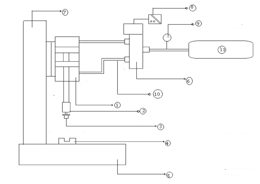
47
next corresponding punch or rivet. Once the punch or rivet is finished then the
microcontroller, timer and relay will get ready for the feed of the sheet metal for next
punch or rivet through automation. The time duration of the consecutive punch or rivet
can be adjusted with the help of microcontroller, timer and relay.
Figure 4.11 Schematic Diagram
1. Pneumatic Cylinder
2. Tool Holder
3. Tool(Punch or Rivet)
4. Bottom die
5. Base Frame
6. Directional Control Valve
7. Frame
8. Control Circuit
48
9. Pressure Gauge
10. Polyurethane Tube
11. Compressor
4.11.3 Design Calculation
Cutting Force=L * t* Tmax
L - perimeter of the punch hole.
t - thickness of the sheet.
Tmax – max tensile strength.
L = 2πr (D=10mm) = 2*3.14*5 = 31.41mm
t = 0.5mm
Tmax = 180 N/mm2
Cutting force = 31.41 * 0.5 * 180 = 5654.86678 N.
Stripping Force = 10 % - 20 % of cutting force.
15 % of cutting force = (15/100) *5654.86678 = 848.2300 N
Press force = Cutting force + stripping force
= 5654.86678 N + 848.23 N
= 6503.097N
Reduced force = 0.37*press force
= 0.37 * 6503.097 N
= 2438.66137 N
For selecting cylinder bore diameter
F= P*A
P = working pressure = 8 bar
A = area of the cylinder=(π/4)*d2
49
2438.66137=0.8*(3.14/4) *d2
d=62.99 mm = 63 mm (Standard size )
Force realised by the cylinder at 8 bar F = P*A
F = 0.8*(3.14/4)*63*63
F = 2492.532 N.
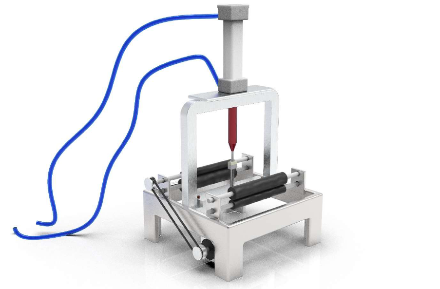
50
CHAPTER 5
RESULTS AND DISCUSSIONS
Figure 5.1 3D Model
Based on the design calculation, the 3D model (as shown in the figure) of the auto feed
pneumatic punching and riveting machine is done in solid works software. With this 3D
model, the fabrication of the auto feed pneumatic punching and riveting machine is
done. The project work has provided a great opportunity and experience to use our
limited knowledge. Gained lot of knowledge while doing 3D model in solid works
software.

51
Table 5.1 Cost Estimation
S.NO
Parts
Quantity
Material
Amount (Rs)
1.
Pneumatic Double -acting
Cylinder
1
Mild Steel
1,428
2.
5/2 Directional Control Valve
1
Aluminium
1356
3.
Pneumatic Hose Pipes
4
Polyurethane
405
4.
Frame (Stand)
1
Mild Steel
499
5.
Microcontroller
1
Arduino
2510
6.
Rollers
4
Mild Steel
875
7.
Punching Tool
1
High Speed
Steel
580
8.
Riveting
T
ool
1
High Speed
S
teel
575
Total: Rs 9,228
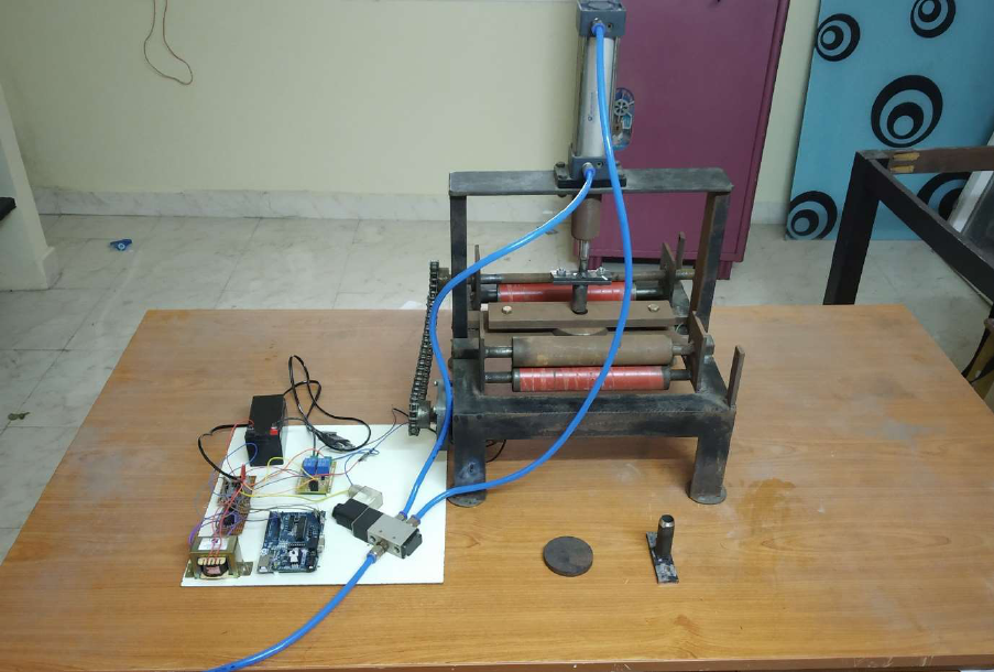
52
The auto feed pneumatic punching and riveting machine is successfully fabricated
within the short period of time. By doing this project lots of knowledge has been gained
based on the planning, purchasing, assembling and machining. The auto feed
pneumatic punching and riveting machine is working successfully and this will be the
example for developing a punching machine at very low cost. This pneumatic punching
machine is easy to understand and work even a beginner will work comfortably in this.
This machine will clear all the problems based on the automation and the errors
happened during the manufacturing in the industries. The changes in the parts can be
made easily based on the customer need and also the manufacturer requirements.
Figure 5.2 Full View
The figure 5.2 shows the full view of the pneumatic punching and riveting machine.
When the compressed air at the pressure of 10 bar is supplied to the one end of the
pneumatic cylinder the pressure below the piston is lower than above the piston so the
piston will move from the top dead centre to the bottom dead centre and the punch or
53
rivet is done. The punch or the rivet tool is attached to the piston end with the help of
the three jaw chuck. The advantage of three jaw chuck is once the punching is finished
then the rivet tool is attached to it for riveting. The punch or rivet tool is guided to the
sheet metal using a die at the bottom. The die is also used to prevent the bending of
the sheet metal and also to prevent the deformation of the sheet metal. When the piston
head reaches the maximum stroke length the compressed air is supplied to another
end of the pneumatic cylinder, due to this the pressure above the piston is lees when
compared to the below. This high pressure of the compressed air moves the piston
from bottom dead centre to the top dead centre and the punch or rivet tool is now free
from the sheet metal. And the pneumatic cylinder is ready for the next corresponding
punch or rivet. Once the punch or rivet is finished then the microcontroller, timer and
relay will get ready for the feed of the sheet metal for next punch or rivet through
automation. The time duration of the consecutive punch or rivet can be adjusted with
the help of microcontroller, timer and relay.
.
54
CHAPTER 6
SUMMARY AND CONCLUSION
The Auto Feed Pneumatic Punching and Riveting Machine can be used as a
replacement for convectional Punching machines like handheld ones which are not
precise and Hydraulic machines which are not cost-efficient and the maintenance cost
will also be high. But the pneumatic auto feed punching and the riveting machine is low
in cost and have less maintenance. Thus, the fabrication of this model helps to achieve
low-cost automation. The operating procedure of this machine is very simple when
compared to other machines, so any person can operate it. By using more technique
this model can be modified and developed based on our requirements. In addition to
this the model can be improved to further extend like
• It can be modified based on the requirements.
• Multiple cylinder systems can be put into action according to the need of
pressing effort.
55
REFERENCES
[1] A.S. Aditya Polapragada, K. Sri Varsha, pneumatic Auto feed punching machine;
International Journal of Engineering Research & Technology (IJERT) Vol. 1 Issue 7,
September – 2012.
[2] Butterworth, Heinemann, sheet metal forming properties: ISBN 0 7506 5300 0,
Typeset by Laserwords Private Limited, Chennai, India Printed and bound in Great
Britain,2002, PgNo: 10 to 21
[3] Enrico Armentani, Alessandro Greco, Alessandro De Luca, Raaele Sepe, Analysis
on the fatigue behaviour of rivet joints; MDPI Applied science Published: 13 May 2020.
[4] Kundan Kumar, V. Sree Harsha, Auto roll punching machine; international journal
of innovative research in science, engineering and technology vol-5, special issue 8,
May 2016.
[5] Kyoung-Yun Kim, Jaemun Sim, Noor-E Jannat, Fahim Ahmed, Sattar Ameri,
Challenges in Riveting Quality; 29th International Conference on Flexible Automation
and Intelligent Manufacturing (FAIM2019), June 24-28, 2019, Limerick, Ireland
[6] Madhanmohan.K, Mohan Kumar.V, Lokesh.K, Sensor based auto punching
conveyer international journal of innovative research in science, engineering and
technology vol-9, issue no 3, May 2019.
[7] Mohamed Ben Bettaieb, Farid Abed-Meraim, Theoretical analysis of stress on
sheet metal formability; International Journal of Mechanical
Sciences, Elsevier, 2017.
[8] P.Goyal, G.Srivastava, R.Singh, N.Singh, Review on Pneumatic Punching
Machine and Modification in Punch Tool to Reduce Punching Force Requirement;
International Journal of Engineering Technology Science and Research, Volume 2
Issue 2, 2015.
[9] Romit Singh, Mohan Singh, Sri varsha, Analysis of stress in punching tool;
International Journal of Engineering Technology Science and Research 2020.
56
[10] Shubhangi.S.Shetake Sumeet.A.Padwalkar, Abhishek.S.Gunje, Advita.A.Ingale,
Sushil.V.Rawale, AUTOMATIC PNEUMATIC PUNCHING MACHINE International
Research Journal of Engineering and Technology volume-7, issue:5 may-2020.
[11] Sree Rajendra, Arun .s, Vijayavithal Bongale, Automatic Punching Machine: A
Low Cost Approach, International Journal of Advanced Mechanical Engineering
Volume 4, Number 5, 2014.
[12] Sudeep Kelaginamane*, Sridhar D. R, PLC Based Pneumatic Punching Machine;
international journal of innovative research in science, engineering and technology vol-
5, issue 8, May 2015.
[13] Utkarsh singh, Sharma sree, Automatic Pneumatic Hole Punching Machine; ,
International Journal of Advanced Mechanical Engineering Volume 3, Number 6, 2014.
57
APENDIX
