
International Research Journal of Engineering and Technology (IRJET) e-ISSN: 2395-0056
Volume: 06 Issue: 05 | May 2019 www.irjet.net p-ISSN: 2395-0072
© 2019, IRJET | Impact Factor value: 7.211 | ISO 9001:2008 Certified Journal | Page 1140
Design and Development of Pneumatic Punching Machine
Viraj N. Suryawanshi
1
, Nilesh V.Wakade
2
, Prof. Prashant A. Narwade
3
1,2
Student in Mechanical Engineering, D.V.V.P.C.O.E.A’nagar, Maharashtra, India
3
Professor in Mechanical Engineering, D.V.V.P.C.O.E.A'nagar, Maharashtra, India
----------------------------------------------------------------------***---------------------------------------------------------------------
Abstract: A pneumatic punching machine is always a better choice than a hydraulic punching machine to produce similar
products if it is suited for the method. It is comparatively more economical for production of large quantities of products as it
uses compressed air rather than some hydraulic fluid which is rather expensive. A pneumatic punching machine uses
compressed air to generate high pressure to be applied on the piston. A solenoid valve controls the directional flow of air into
and out of the cylinder. Polyurethane tubes are used for pressure transmission from the pneumatic cylinder to the punch
assembly. The high-pressure air fed to the punch, forces it on the material and as the punch descends upon the sheet, the
pressure exerted by the punch first cause the plastic deformation of the sheet.
Key Words: Compressed Air, Economical, Solenoid Valve, Polyurethane tubes, Pneumatic Cylinder
1.
INTRODUCTION
Pneumatics, from the Greek (pneumatikos, coming from the wind) is the use of pressurized gases to do work in science
and technology. Pneumatics was first documented by Hero of Alexandria in 60 A.D., but the concept had existed before
then. Pneumatic products represent a multi-billion dollar industry today. Pneumatic devices are used in many industrial
applications. Generally appropriate for applications involving less force than hydraulic applications, and typically less
expensive than electric applications, most pneumatic devices are designed to use clean dry air as an energy source. The
actuator then converts that compressed air into mechanical motion. The type of motion produced depends on the design of
the actuator. Pneumatics is employed in a variety of settings. In dentistry applications, pneumatic drills are lighter, faster
and simpler than an electric drill of the same power rating (because the prime mover, the compressor, is separate from the
drill and pumped air is capable of rotating the drill bit at extremely high rpm). Pneumatic transfer systems are employed
in many industries to move powders and pellets. Pneumatic tubes can carry objects over distances. Pneumatic devices are
also used where electric motors cannot be used for safety reasons, such as mining applications where rock drills are
powered by air motors to preclude the need for electric motors deep in the mine where explosive gases may be present.
Pneumatic cylinders are generally less expensive than hydraulic cylinders of similar size and capacity.
1.1
OBJECTIVE OF PROJECT
To design and develop such a pneumatic punching machine which uses compressed air to generate high pressure to be
applied on piston and this high-pressure air fed to punch, forces it on the material. And thus punching operation is
performed.
2.
LITERATURE SURVEY
Girish Gharat et all (1): This project has met its objective to produce a C-Frame Pneumatic Press and its function is
limited to V-Bending and Punching. We designed a pneumatic press which costs less than that available in the market. We
are very good at what we have done and had fun doing it. Our pneumatic press is useful to do metal forming operations
and as it is a 2 tonne capacity press.
Anand Kumar Singh et all (2): Pneumatic system is better than hydraulic system and mechanical system in terms of
maintenance, cost, accuracy, Productivity. Based on calculation project model work on max 42 bar punching force
K.K.Alaneme et all (3): The failure of punch die materials used in the production of cable trays has been investigated. The
analysis show that the short service life of the indigenous die component is due to incorrect heat-treatment which did not
remove the cold-worked structure in built in the material during production, thus resulting in inferior toughness and/or
fatigue resistance .It was equally identified that occasional misalignment of the mould upper die teeth and lower die plate
due to over exertion of the machine contributes to failure of the die material.
International Research Journal of Engineering and Technology (IRJET) e-ISSN: 2395-0056
Volume: 06 Issue: 05 | May 2019 www.irjet.net p-ISSN: 2395-0072
© 2019, IRJET | Impact Factor value: 7.211 | ISO 9001:2008 Certified Journal | Page 1141
Shridhar D. R. et all (4): In this paper design and control method of sheet metal punching machine is explained. By using
Programmable Logic Controllers as the controller of the whole system, good and easy control over the system can be
achieved. Manufacturing lead time of the system is reduced by developing automatic feeding mechanism, worker safety is
increased by reducing the human participation in the process and the problem of angular misalignment of sheets is also
reduced.
3.
EXPERIMENTAL SETUP
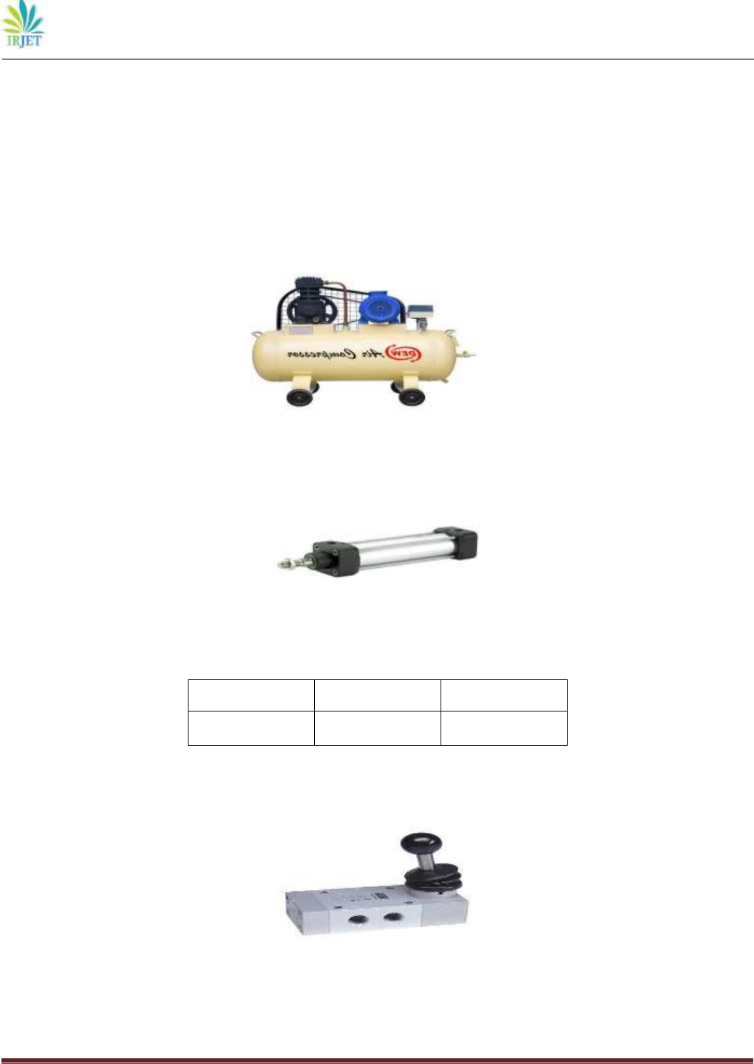
1. COMPRESSOR: A compressor is a machine that compresses air or another type of gas from a low inlet pressure
(usually atmospheric) to a higher desired pressure level. This is accomplished by reducing the volume of the
gas. Air compressors are generally positive displacement units.
Fig3.1. Air Compressor
2. Pneumatic Cylinder: The cylinders convert the energy of the compressed air into linear motion which extend or
retract the piston rod.
Fig3.2. Pneumatic Cylinder
Selected pneumatic cylinder is listed below-:
Type of Cylinder
Bore Diameter
Stroke Length
Double Acting Cylinder
50 mm
100 mm
3. Direction Control Valve: Direction control valve is used to give proper direction to the working fluid for extension
and retraction of the piston in cylinder. Fig.3.1 shows direction control valve selected and Fig.3.2 shows mechanism of
operation.
Fig3.3. 5/2 hand lever operated DCV
International Research Journal of Engineering and Technology (IRJET) e-ISSN: 2395-0056
Volume: 06 Issue: 05 | May 2019 www.irjet.net p-ISSN: 2395-0072
© 2019, IRJET | Impact Factor value: 7.211 | ISO 9001:2008 Certified Journal | Page 1142
Fig3.4. Mechanism of 5/2 DCV
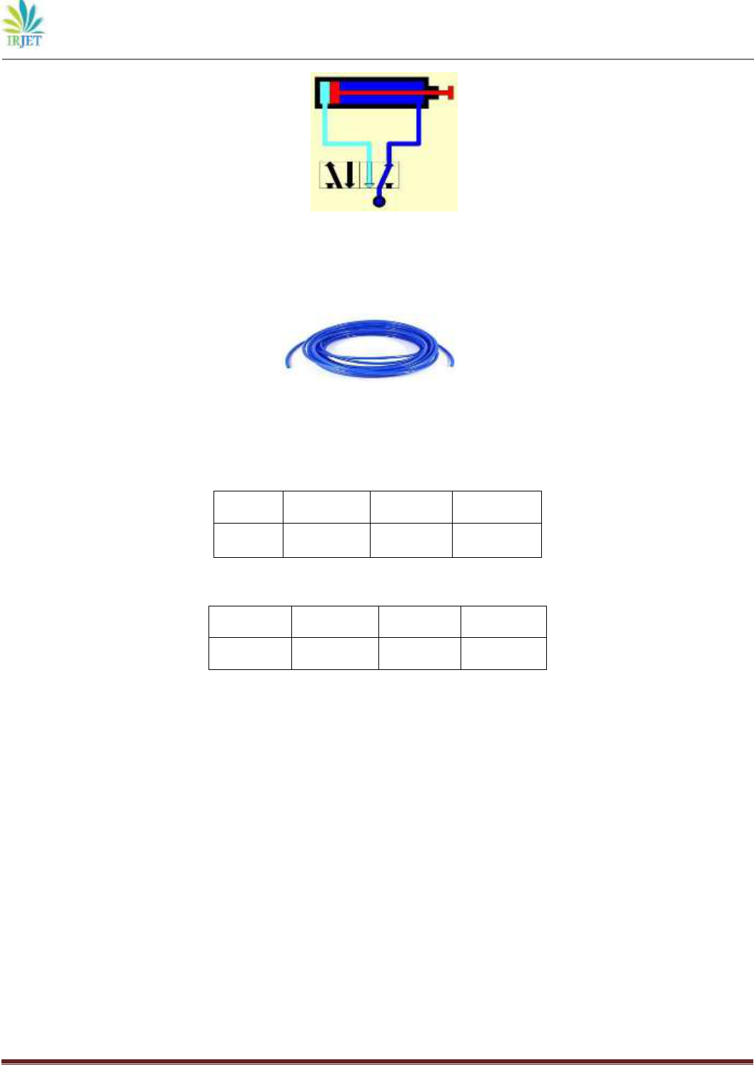
4. Polyurethene tubes: Polyurethene tubes are used for transmission of pneumatic fluid i.e. compressed air.
Polyurethene combines the best properties of both plastic and rubber. It offers abrasion and tear resistance, high tensile
and elongation values, and low compression set.
Fig3.5. Polyurethene Tube
5. Bed and Frame: Frame is the structure used for supporting pneumatic cylinder and Bed is the structure used for
handling the material to be punched.
For bed
Material
Length(cm)
Width(cm)
Height(cm)
Mild Steel
60
60
95
For frame
Material
Length(cm)
Width(cm)
Height(cm)
Mild Steel
20
20
35
6. Punch and Die: The sheet metal used is called strip or stock. The punch which is held in the punch holder is bolted to
the press ram while die is bolted on the press table. During the working stroke, the punch penetrates the strip, and on
the return stroke of the press ram the strip is lifted with the punch, but it is removed from the punch by the stripper
plate. The stop pin is a gage and it sets the advance of the strip stock within the punch and die. The strip stock is butted
against the back stop acting as a datum location for the center of the blank.
4. Working of system
The compressed air from the compressor at the pressure of 8 to 10 bar is passed through a pipe connected to the hand
lever operated valve with one input. The hand lever operated valve has two outputs pressure below the piston is more
than the pressure above the piston. So these move the piston rod from BDC to TDC. This force acting is passed on to punch
which also moves downwards. The punch is guided by a punch guide who is fixed such that the punch is clearly guided to
the die. The materials are in between the punch and die. So as the punch comes down the materials are sheared to the
required profile and one input. The air entering into the input goes out through two outputs. When the hand lever valve is
pressed, due to the high air pressure at the BDC of the piston, the air of the punch and the blank is moved downwards
through the die clearance. When the piston is at the extreme point of the stroke length, the exhaust valve is opened and the
air is exhausted through it and when hand lever operated valve is release the pressurized air come in at the TDC of the
piston and it pushes the piston from
International Research Journal of Engineering and Technology (IRJET) e-ISSN: 2395-0056
Volume: 06 Issue: 05 | May 2019 www.irjet.net p-ISSN: 2395-0072
© 2019, IRJET | Impact Factor value: 7.211 | ISO 9001:2008 Certified Journal | Page 1143
TDC to BDC. So the one side of the air is pulled downwards and the other side is lifted upwards. So the punch is therefore
pulled upwards from the die. Now the piston reaches the BDC of the required stroke length. Now the material is fed and
the next stroke of the piston is made ready.
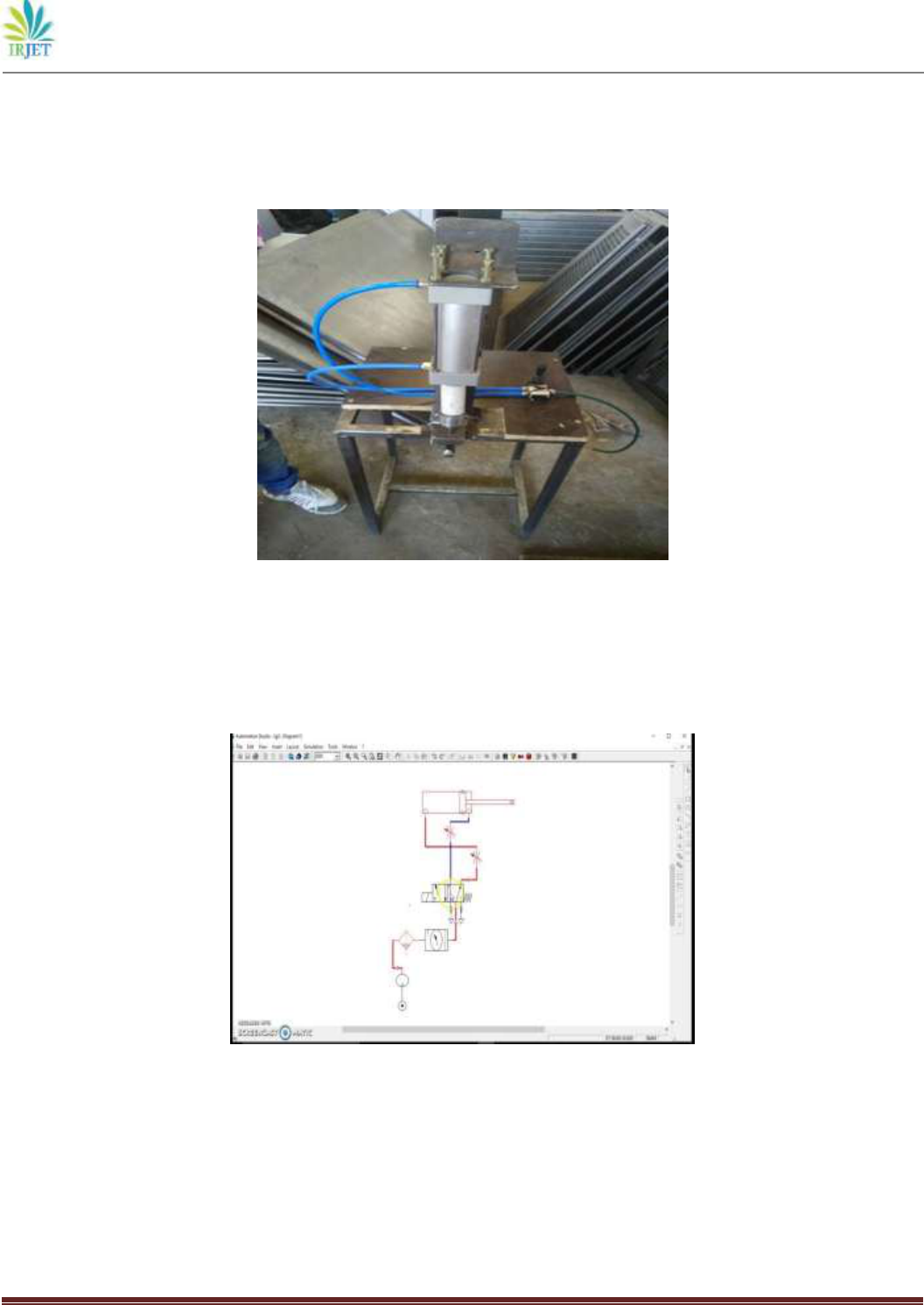
5. Assembly
Fig.5 Assembly of Project
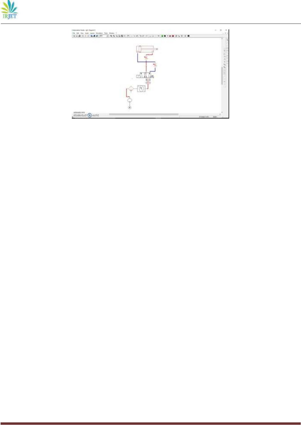
6. Simulation
Automation Studio is a circuit design, simulation and project documentation software for fluid power systems and
electrical projects conceived by Famic Technologies Inc.. It is used for CAD, maintenance and training purposes. Mainly
used by engineers, trainers and service and maintenance personnel.
Fig. 6.1 Extension of Cylinder
International Research Journal of Engineering and Technology (IRJET) e-ISSN: 2395-0056
Volume: 06 Issue: 05 | May 2019 www.irjet.net p-ISSN: 2395-0072
© 2019, IRJET | Impact Factor value: 7.211 | ISO 9001:2008 Certified Journal | Page 1144
Fig. 6.2 Retraction of Cylinder
Conclusions: This project has met its objective to produce a hole by pneumatic force. We are very good at what we have
done and had fun doing it. We can do simple operations like punching, which is very useful and helpful to do small works
at our college. We chose a simple c-frame machine which occupies less space which any one can operate.
We tested our project by punching the sheet metal. As our project is based on manufacturing of pneumatic punching
further modifications can be done and increase its applications.
Future Extension:
We contemplate the following future features which can be incorporated into this project:-
1) Automation of pneumatic punching machine
2) Accident avoiding systems by adding LDR sensors
3) Improvements in pneumatic machine by adding components like timers, silencers, etc.
References:
(1) Design and Fabrication of Pneumatic Punching and Bending Machine, 2015,IJSRD,Vol.3,Issue02,2015
(2) Design and Development of Pneumatic Punching machine , Anand Kumar Singh,IJTRE,Volume4,Issue 11,July2017
(3) Failure analysis of mould dies of an industrial punching machine, K.K.Alaneme,ELSEVIER,14 January
2009,Enginnering Failure Analysis 16(2009)2043-2046
(4) PLC Based Pnenumatic Punching Machine, Sridhar D.R.,2015,Journal of Mechanical Engineering and
Automation2015,5(3B):76-80
(5) Development of a micro-forming system for micro- punching process of micro-hole arrays in brass foil”, JieXu,
Bin Guo, Debin Shan, Chunju Wang, Juan Li , YanwuLiuc, DongshengQu , 2012 ,Journal of Materials Processing
Technology 212 ,2238– 2246.
(6) A new design method for single DOF mechanical presses with variable speeds and length-adjustable driving
links”, Ren-Chung Soong, 2010, Mechanism and Machine Theory 45, 496–510.
(7) Development of Micro Punching System”, B. Y.Joo', S. I. Oh, B. H. Jeon.1980

International Research Journal of Engineering and Technology (IRJET) e-ISSN: 2395-0056
Volume: 06 Issue: 05 | May 2019 www.irjet.net p-ISSN: 2395-0072
© 2019, IRJET | Impact Factor value: 7.211 | ISO 9001:2008 Certified Journal | Page 1145
BIOGRAPHIES:
Viraj Narayan Suryawanshi
B.E. Mechanical Engineering (2015-2019) D.V.V.P.C.O.E.Ahmednagar Maharashtra
India
Nilesh Vijay Wakade
B.E. Mechanical Engineering (2015-2019) D.V.V.P.C.O.E.Ahmednagar Maharashtra
India
Guided by:
Prof. Prashant A. Narwade Asst. Professor
Dept. of Mechanical Engineering D.V.V.P.C.O.E.Ahmednagar Maharashtra
India
